Volvo S60 I (2005) – fuse box diagram
Year of manufacture: 2005.
Lighter fuse (power socket) in Volvo S60 (2005). Is fuse 11 in the fuse box in the passenger compartment.
Relay/fuse box in the engine compartment
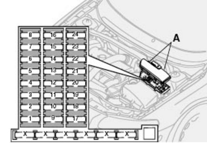
| No. | Description | Amps [A] |
| 1 | – | – |
| 2 | Additional lights (optional equipment) | 20 |
| 3 | Throttle module (non-turbo models) | 10 |
| 4 | Oxygen sensor | 20 |
| 5 | Crankcase Vent Heater;
Solenoid valves; Fuel leakage sensor. |
10 |
| 6 | Mass airflow sensor;
Engine control module; Injectors. |
15 |
| 7 | – | – |
| 8 | Air conditioning compressor;
Accelerator pedal position sensor; Electronic case fan. |
10 |
| 9 | – | – |
| 10 | – | – |
| 11 | Ignition Coils | 20 |
| 12 | – | – |
| 13 | Cleaners | 25 |
| 14 | ABS | 30 |
| 15 | Headlight Washer Nozzles
(some models). |
35 |
| 16 | – | – |
| 17 | Dipped beams on driver’s side | 20 |
| 18 | Front parking lights | 15 |
| 19 | ABS | 30 |
| 20 | Passenger side low beam headlights | 20 |
| 21 | Fuel Pump | 15 |
| 22 | Starter | 35 |
| 23 | Motor control module;
Engine relay. |
10 |
| 24 | – | – |
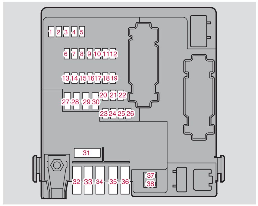
Fuse box on the edge of the dashboard
| No. | Description | Amps [A] |
| 1 | Electrically operated driver’s seat
(optional). |
25 |
| 2 | Electric passenger seat
(optional). |
25 |
| 3 | Air conditioning system fan | 30 |
| 4 | Control unit – front passenger door | 25 |
| 5 | Control unit – driver’s door | 25 |
| 6 | Ceiling lighting;
Upper electrical control module. |
10 |
| 7 | Opening roof (optional) | 15 |
| 8 | Ignition;
SRS system; Motor control module; Immobilizer. |
7,5 |
| 9 | Onboard Diagnostics;
Light switch; Steering wheel angle sensor; Steering wheel control module. |
5 |
| 10 | Sound System | 20 |
| 11 | Audio System Amplifier | 30 |
| 12 | Navigation system display (optional) | 10 |
| 13 | – | – |
| 14 | – | – |
| 15 | – | – |
| 16 | – | – |
| 17 | – | – |
| 18 | – | – |
| 19 | – | – |
| 20 | – | – |
| 21 | – | – |
| 22 | – | – |
| 23 | – | – |
| 24 | – | – |
| 25 | – | – |
| 26 | – | – |
| 27 | – | – |
| 28 | – | – |
| 29 | – | – |
| 30 | – | – |
| 31 | – | – |
| 32 | – | – |
| 33 | – | – |
| 34 | – | – |
| 35 | – | – |
| 36 | – | – |
| 37 | – | – |
| 38 | – | – |
Passenger compartment fuse box
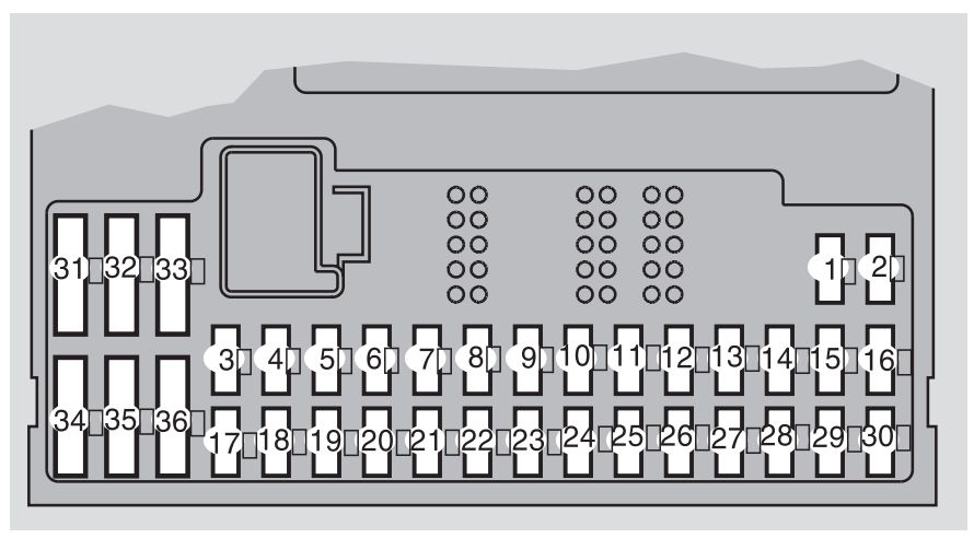
| No. | Description | Amps [A] |
| 1 | Heated passenger seat (optional) | 15 |
| 2 | Heated driver’s seat (optional) | 15 |
| 3 | Horn | 15 |
| 4 | – | – |
| 5 | – | – |
| 6 | – | – |
| 7 | – | – |
| 8 | Alarm siren | 5 |
| 9 | Interrupting the power supply to the light switch | 5 |
| 10 | Dashboard;
Air conditioning system; Electrically operated driver’s seat (optional). |
10 |
| 11 | 12 V power outlets – front and rear seats | 15 |
| 12 | – | – |
| 13 | – | – |
| 14 | Headlamp Wipers (S60 R) | 15 |
| 15 | ABS;
STC/DSTC. |
5 |
| 16 | Power steering;
Bi-xenon headlights (optional). |
10 |
| 17 | Front fog light
on the driver’s side (optional). |
7,5 |
| 18 | Front fog light
on the passenger side (optional). |
7,5 |
| 19 | – | – |
| 20 | – | – |
| 21 | Transmission control module;
Reverse gear block (M66). |
10 |
| 22 | Driving lights on the driver’s side | 10 |
| 23 | Driving lights on the passenger side | 10 |
| 24 | – | – |
| 25 | – | – |
| 26 | – | – |
| 27 | – | – |
| 28 | Electrically operated passenger seat (optional);
Audio system. |
5 |
| 29 | – | – |
| 30 | – | – |
| 31 | – | – |
| 32 | – | – |
| 33 | Vacuum Pump | 20 |
| 34 | Washer Pump,
Headlamp cleaners (S60 R). |
15 |
| 35 | – | – |
| 36 | – | – |
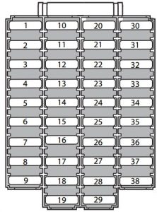
Fuses in the trunk
| No. | Description | Amps [A] |
| 1 | Support Lights | 10 |
| 2 | Parking lights;
Fog lights; Cargo compartment lighting; License plate illumination; Stop lights. |
20 |
| 3 | Accessory control module | 15 |
| 4 | – | – |
| 5 | Rear electronics module | 10 |
| 6 | CD switch (optional);
Navigation system (optional). |
7,5 |
| 7 | Trailer wiring (30 wires) | 15 |
| 8 | 12 V socket – load compartment | 15 |
| 9 | Rear passenger side door –
glass lifting, windshield deactivation function. |
20 |
| 10 | Driver’s side rear door –
window elevator, windshield deactivation function. |
20 |
| 11 | – | – |
| 12 | – | – |
| 13 | – | – |
| 14 | – | – |
| 15 | – | – |
| 16 | – | – |
| 17 | Audio Accessories | 5 |
| 18 | – | – |
| 19 | – | – |
| 20 | Trailer wiring (15 wires) – optional | 20 |
| 21 | – | – |
| 22 | – | – |
| 23 | Four Wheel Drive | 7,5 |
| 24 | Four-C chassis system (optional) | 15 |
| 25 | – | – |
| 26 | Parking assistant (optional) | 5 |
| 27 | Main fuse:
trailer wiring, FourC, parking assistance, four-wheel drive. |
30 |
| 28 | Central locking system | 15 |
| 29 | Lighting on the driver’s side of the trailer:
parking lights, rotate the signals. |
25 |
| 30 | Trailer passenger side lighting:
Parking light, brake light, fog light, indicator. |
25 |
| 31 | Main fuse:
fuses 37 and 38. |
40 |
| 32 | – | – |
| 33 | – | – |
| 34 | – | – |
| 35 | – | – |
| 36 | – | – |
| 37 | Heated rear window | 20 |
| 38 | Heated rear window | 20 |