Volkswagen UP! – Fuse box diagram
Year of manufacture: 2011, 2012, 2013, 2014, 2015, 2016, 2017.
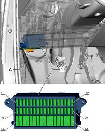
Cigarette lighter fuse (power outlet) in the Volkswagen UP! Is fuse 36 in the engine compartment fuse box.
Location

- Fuse holder D -SD-
- Fuse holder C -SC-
- Fuse Holder B -SB-
- Fuse holder A -SA-
Fuse holder installation location A -SA-

| Number | Amps [A] | Description |
| SA1 | 150 175 * 2 |
Alternator -C- |
| SA2 | 30 | Amplifier -R12- |
| SA3 | 110 | Fuse holder C -SC-;
Main Relay -J271-; Terminal 75 1 supply voltage relay -J680-; |
| SA4 | 40 50 * 3 |
Power steering controller -J500- |
| SA5 | 40 | ABS control unit -J104- |
| SA6 | 40 | Radiator Fan Controller -J293- |
| SA7 | 50 | Automated manual transmission control unit -J514-. * 1 |
| 1 – Depends on the equipment 2 – Only models with start/stop system 3 – From the May 2013 model year |
||
Fuse holder installation location B -SB-
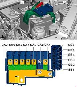
| Number |
Amps [A] | Description |
| SB1 | 25 | ABS control unit -J104- |
| SB2 | 30 | Radiator fan thermal switch -F18-;
Radiator fan controller -J293-. |
| SB3 | 5 7,5 * 1 |
Radiator Fan Controller -J293-;
S-clamp ignition/starter switch -D-. |
| SB4 | 10 | ABS control unit -J104- |
| SB5 | 5 7,5 * 1 |
On-board power control unit -J519- |
| SB6 | 30 | Fuse holder C -SC-;
Ignition/starter switch -D-. |
| 1 – Starting with the May 2013 model | ||
Fuse holder C -SC-
| Number |
Amps [A] | Description |
| 1 | 5 7,5 * 1 |
Instrument panel insert -K-;
Engine controller -J623-; Radiator fan controller -J293-; |
| 2 | 15 | Air conditioning system relay -J32-;
Air conditioning system control unit -J301-; Diagnostic connector -U31-; High pressure transmitter -G65-; |
| 3 | 7.5 | Brake light switch -F-;
Clutch pedal switch -F36-; Camshaft control valve 1 -N205-; |
| 4 | 7.5 | On-board power control unit -J519-.
Light switch -E1-; Light switch; Daytime Running Lights; Driving lights. |
| 5 | 5 7,5 * 1 |
On-board power control unit -J519-;
Ignition/start switch -D-; CCS switch -E45-; |
| 6 | 5 7,5 * 1 |
Range adjuster for right side reflector -E102-;
Range control motor for left headlight -V48-; Right headlight range control motor -V49-; Mirror adjustment switch -E43-; |
| 7 | 10 | Gear shift lever -E313- |
| 8 | 7.5 | Automated manual transmission control unit -J514-;
Gear shift lever -E313-; |
| 9 | 7.5 | Airbag control unit -J234-
Instrument panel center switch module 2 -EX35- |
| 10 | 5 7,5 * 1 |
Parking aid control unit -J446- |
| 11 | 10 | Right-Turn Beam Lamp -M31- |
| 12 | 5 7,5 * 1 |
Dashboard insert -K-
Rear left fog lamp -L46-. Dashboard control unit -J285-. * 1 On-board power control unit -J519- * 1 |
| 13 | 10 | Low beam lamp left -M29- |
| 14 | 15 | Rear wiper motor -V12- |
| 15 | 15 | Light Switch -E1- |
| 16 | 5 7,5 * 1 |
Terminal 15 supply voltage relay -J329-
Power steering controller -J500- |
| 17 | 15 | Washing machine pump switch
(automatic washer/wiper and headlight washers) -E44-. |
| 18 | 7.5 | Reversing light switch -F4- |
| 19 | 15 | Injector, cylinder 1 -N30- Injector, cylinder 2 -N31- Injector, cylinder 3 -N32- |
| 20 | 5 7,5 * 1 |
ABS control unit -J104-
Emergency brake function sensor module -J939- Steering angle transmitter -G85- |
| 21 | 5 7,5 * 1 |
Right side lamp -M3-;
Right rear light bulb -M2-; License plate light -X-; On-board power control unit -J519-; Light switch -E1- Position Lights |
| 22 | 10 | Daytime running light bulb left -L174-;
Daytime running lamp right -L175-; |
| 23 | 5 7,5 * 1 |
Left side lamp -M1-;
Left side lamp -M4-; |
| 24 | 15 | Blinker headlight switch -E5- |
| 25 | 10 | Windshield washer pump for windshield and rear window -V59- |
| 26 | 5 7,5 * 1 |
Main Courier -J271-;
Instrument panel insert -K-; Steering angle transmitter -G85-; |
| 27 | 7.5 | On-board power control unit -J519-.
Front interior lighting -W1-; Front passenger reading light -W13-; Driver’s side reading lamp -W19-; |
| 28 | 5 7,5 * 1 |
Diagnostic link -U31- |
| 29 | 7.5 | On-board power control unit -J519-. |
| 30 | 5 7,5 * 1 |
On-board power control unit -J519-
Heated exterior mirror on driver’s side -Z4- Heated exterior mirror on the passenger side -Z5- |
| 31 | 10 | Lambda Probe -G39-;
Lambda probe after catalytic converter -G130-; Activated carbon filter solenoid valve 1 -N80-; |
| 32 | 15 | On-board power control unit -J519- – Direction indicator / brake light |
| 33 | 10 | Right-Headlight Bulb -M32- |
| 34 | 10 | Left high beam headlight bulb -M30-;
Instrument panel insert -K-; |
| 35 | – | – |
| 36 | 15 20 * 1 |
Cigarette lighter -U1- |
| 37 | 30 | Air conditioning system control unit -J301-;
Heater control unit -J162-; |
| 38 | 15 | Radio -R- |
| 39 | 30 | Sliding roof adjustment control unit -J245- |
| 40 | 15 | Engine control unit -J623- |
| 41 | 25 | On-board power control unit -J519-
Central locking |
| 42 | 25 | Ignition coil 1 with output stage -N70-;
Ignition coil 2 with output stage -N127-; Ignition coil 3 with output stage -N291-; |
| 43 | 20 | Heated front seat control unit -J774-
Switch module in the center of the instrument panel -EX22- Switch module in center of instrument panel 2 -EX35- |
| 44 | 15 | Fuel pump relay -J17- |
| 45 | 20 | Light switch -E1- |
| 46 | 30 | On-board power control unit -J519-
Heated rear window -Z1- |
| 47 | 25 30 * 1 |
Right windshield regulator switch -E41-;
Driver’s door window elevator control assembly -E512-. * 4 ; Driver’s side central locking unit -F220- * 3; |
| 48 | 20 | On-board power control unit -J519-
Horn tweeter -H2- Bass Horn -H7- |
| 49 | 20 30 * 1 |
On-board power control unit -J519-
Wiper motor control unit -J400-. |
| 50 | 15 20 * 2 |
Left fog lamp -L22-
Right Fog Lamp -L23- On-board power control unit -J519- * 2 |
| 51 | 25 30 * 1,4 |
Left windshield lift switch -E40-;
Driver’s door window elevator control assembly -E512-. * 3 Driver’s side central locking unit -F220- * 4 |
| 1 – Starting with the May 2013 model 2 – Only models with start/stop system 3 – From model November 2014 onwards 4 – Only right-hand drive models |
||
Fuse holder D -SD-

| Number |
Amps [A] | Description |
| SD1 | 5 7,5 * 1 |
Emergency brake function sensor module -J939-;
Emergency braking function relay -J1020- * 1 . |
| SD2 | 5 7,5 * 1 |
Dashboard insert -K- |
| SD3 | 10 15 * 1 |
Radio -R- |
| SD4 | 7.5 | Voltage Converter -A19-;
Starter relay 1 -J906-; Start Relay 2 -J907-; |
| SD5 | – | – |
| SD6 | – | – |
| SD7 | – | – |
| SD8 | – | – |
| SD9 | 15 | On-board power control unit -J519-
Traffic lights on the right; Passing lights; Daytime Running Lights. |
| SD10 | 15 | On-board power control unit -J519-
Traffic lights on the left; Passing lights; Daytime Running Lights. |
| SD11 | 30 | Departure Relay 1 -J906-;
Start Relay 2 -J907-. |
| SD12 | 30 | Voltage Converter -A19- |
| 1 – Starting with the May 2013 model | ||