Volkswagen Touareg GP – fuse box diagram
Year of manufacture: 2002, 2003, 2004, 2005, 2006, 2007, 2008, 2009, 2010.
Cigarette lighter fuse (power outlet) in the Volkswagen Touareg GP Is fuses 1, 3 and 5 (front 12 volt socket) in the fuse box on the dashboard.
Fuse 1 is: cigarette lighter + 12v socket in center tunnel for rear passengers;
Fuse #3 is: 12v outlet in trunk;
Fuse #5 is: driver’s 12v socket (through ASB cable) and 12v socket in trunk.
System
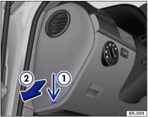
These drawings show the location of the main fuses and relay boxes.


Box on the left side of the dashboard
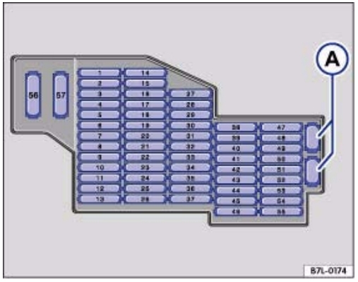
Description
A – Backup fuses
| 1 | 20A cigarette lighter |
| 2 | 5A Parking heater (timer, sensor, pump);
15A Circulation pump relay. |
| 3 | 20A Additional sockets (12V) |
| 4 | 20A Parking Heater – Heater |
| 5 | 20A Socket Relay |
| 6 | 15А KESSY |
| 7 | 5A Diagnostics;
Multiplex System; Rain and light sensor. |
| 8 | 30A wipers |
| 9 | 15A Glass Washing Pump |
| 10 | 25Window Lifter – Rear Left |
| 11 | 15A Central locking – left |
| 12 | 20A Indoor Lighting |
| 13 | – |
| 14 | 25A Window Lifter – Left Front |
| 15 | 20A Rear Lamp left |
| 16 | 20A audible signal |
| 17 | 10A Directional;
Position lights – left. |
| 18 | 20A SRA relay |
| 19 | 15A Fog lamps |
| 20 | Electric Chair 30A |
| 21 | 15A Additional turn signal light |
| 22 | 30A Side lock, trunk lid control 2 |
| 23 | 10A Rear Cross Latch |
| 24 | 5A Tire pressure monitoring system |
| 25 | 15A Steering column adjustment – electro |
| 26 | 10A Airbag control unit;
Front passenger airbag deactivation; Clutch pedal switch. |
| 27 | 5A Switch to turn off the interior monitoring system, interior lighting; |
| 28-32 | Reservation |
| 33 | 15A Steering wheel heating;
Steering column control unit. |
| 34 | 5A Seat heating sensor;
Interior safety monitoring. |
| 35 | 15A Cross beam, high beam;
30A On-board power control unit. |
| 36 | 10A Powered by on-board battery |
| 37 | – |
| 38 | 10A Braking Signals |
| 39 | 5A Relay for ignition system, air conditioning, seat heating, instrument panel |
| 40 | 5A Instrument Panel |
| 41 | 15А KESSY |
| 42 | Electric Hatch 30A |
| 43 | Subwoofer 30A |
| 44 | 30A electric seat |
| 45 | 30A electric seat |
| 46 | – |
| 47 | 10A Inter-axle differential lock control unit |
| 48 | 5A Parking lot heating timer, lane change assistant control unit |
| 49 | 5A Servotronic |
| 50 | 10A Oil level and temperature sensor, fan heater tube (VR6) |
| 51 | 5A air quality sensor;
Tire pressure monitoring system; Diagnostics. |
| 52 | 30A Rear Windshield Wiper |
| 53 | 5A Security surveillance of the interior space of the passenger compartment;
Switching unit for exterior lighting; Heated mirrors. |
| 54 | 10A Headlight range control |
| 55 | 15A power fan relay (speed 2) |
| 56 | 40A Air Conditioning |
| 57 | Bitron 40A Fan Control Motor |
On the right side of the dashboard
Located on the right edge of the dashboard.
 Description
| 1 | 15A Trailer recognition control unit |
| 2 | 5A Parktronic;
Compass. |
| 3 | 15A Trailer control unit |
| 4 | Phone 5A |
| 5 | 15A Trailer recognition control unit |
| 6 | 30A Anti-slip system ESP, ABS |
| 7 | 5A Control box control unit |
| 8 | 20A Additional High Beam |
| 9 | DC 5A Switch |
| 10 | 5A TV Tuner |
| 11 | Radio 10A |
| 12 | 30A Audio amplifier, antenna switch |
| 13 | – |
| 14 | 20A Right rear light;
15A Trunk lid control. |
| 15 | Windshield lifter 25A – right rear |
| 16 | Luggage compartment light 10A |
| 17 | 15A low beam, high beam |
| 18 | 30A Rear window defroster relay |
| 19 | Tipping traction hitch motor 25/30A |
| 20 | 30A Electric seat adjustment 20A;
Inverter with socket, 12V-230V. |
| 21 | 10A Security Alert System;
Spare wheel unlocking. |
| 22 | 25/30A Electrically adjustable right front seat;
Heated front seats. |
| 23 | 10A Air Conditioning |
| 24 | Electric seat adjustment 25/30A |
| 25 | 5A Rear air conditioning console |
| 26 | – |
| 27 | 15A Tire pressure monitoring system;
Ride height control unit. |
| 28 | 10A Automatic remote maintenance |
| 29 | 10A Automatic transmission (automatic gearbox) |
| 30 | 20A winch, relay closer |
| 31 | 25A Rear control unit;
15A Rear cover control unit. |
| 32 | 10A Central locking – right |
| 33 | 10A Alarm system rear control unit;
15A Individual equipment. |
| 34 | Windshield lifter 25A – right front |
| 35 | 10A Direction indicator, parking lights, right;
30A Control panel for front passenger seat adjustment. |
| 36 | 5A Ceiling Module, telephone |
| 37 | – |
| 38 | EPS, ABS |
| 39 | 10A Air conditioning;
5A Windshield heater relay. |
| 40 | 10A Longitudinal lock |
| 41 | 10A Trailer control unit |
| 42 | 5A Radio, garage door opener control |
| 43 | 5A reversing light switch |
| 44 | Heated wash nozzles;
Seat heating regulator. |
| 45 | Reservation |
| 46 | Reservation |
| 47 | 10A Automatic distance control;
Radar sensor; Right headlight module. |
| 48 | Air suspension control unit 10A |
| 49 | Mirrors 5A, telephone |
| 50 | 5A Parktronic;
Turn off ASR and ESP. |
| 51 | Gearbox 20A |
| 52 | Selector 5A |
| 53 | 30A windshield heater relay |
| 54 | 30A Electric trailer brakes;
Windshield heater relay. |
| 55 | 20A Electric steering column |
| 56 | 40A ABS, ESP |
| 57 | 40A Longitudinal lock |
Under-grid mounting box
The relays and fuse box are located in the air intake compartment in the engine compartment.
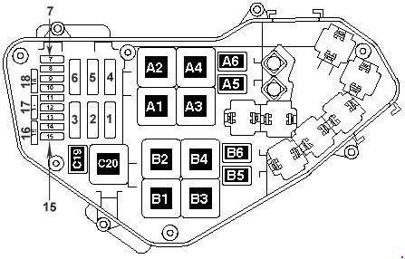
Description
| 1 | 60A Radiator fan control unit, radiator fan |
| 2 | 30A Radiator fan control unit, radiator fan |
| 3 | 40A secondary air pump |
| 4 | 40A secondary air pump |
| 5 | 30A Ignition coil , fuses in relay and fuse box |
| 6 | 30A Ignition coil |
| 7 | 10A Cylinder injector;
Fuel cooling pump relay; 20A Ignition coil. |
| 8 | 10A Injector Cylinder;
20A Ignition coil. |
| 9 | 30A Motronic Controller;
Motor Controller; Diesel injection controller. |
| 10 | 10A High pressure sensor;
Air flow meter; Air conditioning control unit; Alternator connection relay; Auxiliary cooling pump relay; Brake booster relay (3.2 l); Fuel system diagnostic pump; Turbocharger control unit. |
| 11 | 15A oil level and temperature sensor;
Climate controller; Shock dampening solenoid valve; Turbocharger controller; 10A Air conditioning controller. |
| 12 | 5A Secondary air pump relay;
Electric fuel pump relay; 10A 1 absorption solenoid valve, regulator; Glow plug control unit; 20A electronically controlled engine cooling thermostat; High pressure sensor; Coolant circulation relay after shutdown. Engine; Air conditioning controller; Intake camshaft control valve; Intake manifold geometry change motor. |
| 13 | 15A Fuel pressure regulator;
Fuel pump. |
| 14 | 15A Fuel pressure regulator;
Fuel pump 10A Fuel metering valve; |
| 15 | 15A fuel pump relay;
Motronic control unit; Motor control unit. |
| 16 | 10A Parallel Battery Relay;
30A brake master cylinder. |
| 17 | 15A Lambda Probe;
Lambda Probe 30A. |
| 18 | 7.5/15A Lambda probe after catalytic converter |
Relay
| A1 | Glow plug control unit (475) |
| A2 | Terminal 30 power relay (109) / (219) |
| A4 | Fuel pump relay (53) |
| A6 | Fuel cooling pump relay (404) |
| A5 | Additional cooling pump relay (404) |
| A3 | Glow plug control unit (475) |
| B6 | Additional Fuel Pump Relay (449) |
| B7 | Not used |
| B4 | Low heating power relay (100)
Power Relay 1 (100) |
| B3 | High Power Heating Relay (100) |
| B1 | Terminal 30 power relay (219) |
| B2 | Fuel pump relay (53) |
| C20 | Terminal 50 power relay (433) |
| C19 | Fuel propellant pump relay (404) |
Box under the driver’s seat
Located on or near the battery cover.

Description
- Battery master switch
- Power supply relay terminal 15 (100) / (433)
- Second battery charging relay
| SD1 | 150A Fuse box left |
| SD2 | 150A Right fuse box |
| SD3 | 60A Right fuse box |
| SD4 | 60A distribution block, left fuse box |
| SD5 | 60A Terminal 15 Relay |
| SD7 | 250A Parallel Battery Connection |
| SD8 | 150A Socket |
| SD9 | 5A On-board power control unit |
| SD10 | 10A Onboard Power Control Unit |
| SD11 | 5A Starter cable diagnostics |
| SD12 | Not used |
| SD13 | 40A Electric motor for driving height adjustment compressor |
| SD14 | Not used |
Relay box under the dashboard
Located under the front panel on the left side.

Description
| D1 | Servo Controller (476) |
| D2 | Proximity courier (404) |
| D3 | Ride height control compressor relay (373) |
| D4 | Socket Relay (404) |
| D5 | Air conditioning relay (100) |
| D6 | Fresh air blower relay, speed 2 (404) only with manual air conditioning |
| D7 | Heated rear window relay (53) |
| D8 | Circulation pump relay (404) VR6 with auxiliary heater only |
| D9 | Alternator linkage relay (53) |
| E1 | Solar Cell Isolation Relay (79) |
| E2 | Spare Wheel Release Relay (404) |
| E3 | Left Windshield Heater Relay (53) |
| E 4 | Relay recirculation pump (404) |
| E5 | Power supply relay terminal 2 (432) V10 TDI only |
| E6 | Not used |
| E7 | Headlight cleaning relay (53) |
| E8 | Residual heat accumulator relay (404) |
| E9 | Heated windscreen relay, right (53) |