Volkswagen Passat B6 (2005-2010) – Fuse box diagram
Year of manufacture: 2005, 2006, 2007, 2008, 2009, 2010.
Lighter fuse (electrical outlet) on Volkswagen Passat B6 (2005-2010). Are the fuses in the passenger compartment:
Left
Type 1 – Depending on the year of manufacture, a 38 or 41 15A fuse is responsible for the lighter.
Type 2 – In this version, a fuse number 41, 20A, is responsible for the cigarette lighter. And for the additional sockets – 42 for 15A.
Rights
Fuse number 35, 20A, is responsible for the cigarette lighter.
System
- Passenger-side fuse box in the instrument panel
- Box beside the battery
- Box behind the upholstery in the trunk
- Fuse box on driver’s side in instrument panel
- Relay boxes
- Fuse and relay box under the hood
- Main fuse box
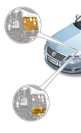
Engine Compartment
The fuse and relay box is located on the left side of the engine compartment and is divided into 2 sections: the mounting box and the high power main fuse section.
Type 1
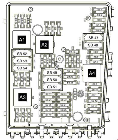
Description
| 1 | 5/15A Automatic transmission controller;
DSG mechatronic unit. |
| 2 | ABS control unit 30A |
| 3 | 20A Convenience system central control unit (to April 2006);
Trailer recognition control unit (from May 2006). |
| 4 | 5A On-board power control unit |
| 5 | 20A Sound Signal |
| 6 | 20A Ignition coils with output stages |
| 7 | 15A Fuel pressure regulator;
5A Clutch pedal position sensor. |
| 8 | 10A Radiator fan control;
Timing valve; Ejection pump valve; Intake manifold handle valve. |
| 9 | 5A Circulation pump relay |
| 10 | 10A Power Relay 2 Motronic;
Lambda probe heating element. |
| 11 | 25/30A Engine control unit |
| 12 | Not used |
| 13 | Not used |
| 14 | Not used |
| 15 | 10A Circulation Pump |
| 16 | 5A Steering column control unit |
| 17 | 5A Instrument cluster control unit |
| 18 | 30A Amplifier, control unit for special vehicles |
| 19 | 15 / 20А Main unit;
Control unit with display of radio system with navigation. |
| 20 | 20A Mobile Phone;
TV; Digital Satellite. |
| 21 | 10A TV Tuner;
Digital satellite tuner. |
| 22 | 7.5A Control unit for the multimedia system |
| 23 | 10A Radiator fan control unit;
5A Magnetic field sensor for compass. |
| 24 | 5/10A Backplane Diagnostic Interface |
| 25 | Not used |
| 26 | 10A Motor control unit;
Motronic power relay. |
| 27 | Not used |
| 28 | Not used |
| 29 | Not used |
| 30 | 20A Additional heater control unit |
| 31 | Wiper motor control unit 30A |
| 32 | 10A Loading Pressure Valve |
| 33 | 15A Fuel pressure regulator;
Lambda probe heating element. |
| 34 | Not used |
| 35 | 20A Relay for auxiliary heater operation |
| 36 | Not used |
| 37 | Not used |
| 38 | Not used |
| 39 | Not used |
| 40 | Not used |
| 41 | Not used |
| 42 | Not used |
| 43 | Not used |
| 44 | 10A Fuel system diagnostic pump |
| 45 | 10A Lambda Probe |
| 46 | 10A Lambda probe heating element 1 behind catalytic converter |
| 47 | 40A On-board power control unit, dipped beams, side lights |
| 48 | 40A On-board power control unit, dipped beams, side lights |
| 49 | On-board power control unit -J519- (power to terminal 15) |
| 50 | 60A Second battery charging relay |
| 51 | Not used |
| 52 | 60A Heated windscreen element |
| 53 | 50A On-board power control unit, left fuse box |
| 54 | 50А Auxiliary air supply motor, glow plug relay |
Relay
A1 – supply voltage of relay terminals 30;
A2 – A4 – reserve.
Type 2
 Description
| 1 | 7.5A Control unit for the multimedia system |
| 2 | ABS control unit 30A |
| 3 | 20A buzzer;
On-board power control unit. |
| 4 | 20A Convenience system central control unit (to April 2006);
25A Trailer recognition system control unit (from May 2006). |
| 5 | 5A Battery monitoring control unit, on-board power control unit |
| 6 | 5A Automatic transmission control unit;
15A DSG gearbox mechatronic unit. |
| 7 | 15A Control unit with display for TV and radio system with navigation;
Main unit; Control unit with display for radio system with navigation; 30A. Voltage stabilizer. |
| 8 | 30A DSG mechatronic gearbox |
| 9 | 5A Steering column control unit |
| 10 | 20A Fuel pump relay (diesel only);
Glow plug control unit; Ignition coils with output stage (cylinders 1 – 4). |
| 11 | 5A Control unit in instrument cluster (only vehicles with Start-Stop system) |
| 12 | 5A Control unit to control the electronics of cell phones, Antenna, TV tuner, digital satellite. |
| 13 | 10A Motronic power relay;
Power relay cl. 30, motor control unit. |
| 14 | 25/30A Engine control unit |
| 15 | 5/10A Backplane Diagnostic Interface |
| 16 | 5A Secondary air pump relay;
10A Exhaust gas recirculation valve; Solenoid valve to limit the boost pressure; Lambda probe heater. |
| 17 | 10A Fuel tank shut-off valve;
40A Low power heating relay (as of November 2006). |
| 18 | 5A Heating Relay;
10A Coolant circulation pump when the engine is turned off; 30A Control unit for the reducing agent heating system. |
| 19 | 30A Amplifier |
| 20 | 5A Additional fuel pump relay;
Radiator fan control unit; Glow plug control unit; 10A Clutch pedal position sensor; Camshaft variable valve 1; 15A Fuel pressure regulator. |
| 21 | 20A Additional heater control unit |
| 22 | Wiper motor control unit 30A |
| 23 | 5A Magnetic field sensor for compass;
Glow plug controller; 10A Electronically controlled engine cooling thermostat;a; Radiator fan controller; Air damper/intake motor; Lambda probe with heating element; Timing and collection. |
| 24 | 10/15A Nitrogen oxide emission sensor control unit;
Lambda probe heater. |
| 25 | 40A On-board power control unit;
Passing lights; High beam; Dimensions. |
| 26 | 40A On-board power control unit;
Passing lights; High beam; Dimensions. |
| 27 | 60A Heated windscreen element |
| 28 | 40/50A Secondary air pump motor;
Glow plug control unit. |
| 29 | 50A On-board power control unit;
X contact discharge relay. |
| 30 | 50A On-board power control unit |
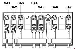
Main fuse box
High power fuses in the form of fusible links.
Type 1
Description
| 1 | 150 / 180A – Generator |
| 2 | 80A Electric motor for electric power steering |
| 3 | 50/80A radiator fan control unit |
| 4 | 80/100A Thermal fuse 1 seat setting, left and right fuse box |
| 5 | Right 80A fuse box (until April 2008);
Driver’s seat thermal regulation fuse 1. |
| 6 | 80/100A Fuse box left and right |
| 7 | ABS control unit 40A |
Type 2
Description
| 1 | 150A – Generator |
| 2 | 80A Electric motor for electric power steering |
| 3 | 50/80A radiator fan control unit |
| 4 | 60A Thermal fuse 1 Seat adjustment, left and right fuse box |
| 5 | 60/80A Thermal fuse seat adjustment 1, left and right fuse box |
| 6 | 80/100A Fuse box left and right |
| 7 | 60А Charging cable for the second battery;
100А Secondary air heater heating element; High power heating relay. |
| 8 | ABS control unit 40A |
In diesel vehicles, the glow plug control unit is located under the fuse and relay box.
Passenger compartment
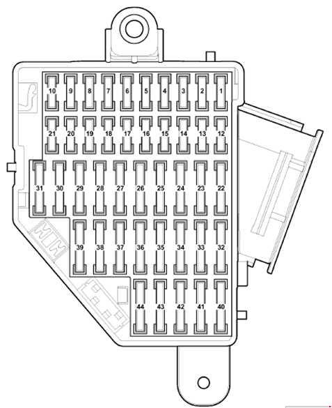
Driver’s side fuse box
Located on the left edge of the instrument panel.

Description – Type 1
Used mainly until April 2008.
| 1 | 10A Diagnostic Connector |
| 2 | 5A ASR and ESP off key;
AUTO HOLD button. |
| 3 | 5A Power Steering |
| 4 | Brake light switch 5A |
| 5 | 10A headlight leveling control, headlight leveling drive motor, left headlight control unit |
| 6 | 5A Trailer recognition control unit |
| 7 | 5A Instrument cluster control unit, data bus diagnostic interface |
| 8 | 5A Rear window curtain switch (until May 2005);
Garage door opening control panel (until May 2005); Rear curtain control (until May 2005); Electrochromic interior rear-view mirror. |
| 9 | Four-wheel drive controller 10A |
| 10 | 5A Motronic power relay;
Motor control unit. |
| 11 | 5A Key for emergency data logger;
Mirror with taximeter; Tachograph. |
| 12 | 10A Driver door controller;
Right rear door controller (as of May 2006). |
| 13 | 10A Light switch, diagnostic connector |
| 14 | 5A Electronic steering column lock control unit |
| 15 | 5A On-board power control unit, front ceiling lamp |
| 16 | 10A Electronic Ignition Lock |
| 17 | 10A Transmitter-receiver module 1 for indoor monitoring system or additional heater;
Rain and light sensor; Vehicle inclination sensor; Alarm siren. |
| 18 | Not used |
| 19 | Not used |
| 20 | Not used |
| 21 | Not used |
| 22 | 10A Air mass meter;
5A Electric fuel pump relay 2. |
| 23 | 10A Heating resistor for crankcase ventilation system (cold climate country version) |
| 24 | 5/20A Reversing switch;
Multifunction switch; Automatic transmission controller; Mechatronic assembly of the DSG gearbox. |
| 25 | 10A injectors (until November 2005);
10A control panel for garage door opening (until April 2006). |
| 26 | 10A Rear window blind switch (as of May 2005);
Rear window shutter control (from May 2005). |
| 27 | 5A Fresh air blower relay;
Climate control unit. |
| 28 | 20A Trailer recognition control unit (as of May 2006). |
| 29 | 20A Trailer recognition control (left tail light, brake light, right/left indicator) (until April 2006);
Electromechanical parking brake controller (from May 2006). |
| 30 | 15A Trailer Detector Controller;
Electromechanical parking brake controller (as of May 2006). |
| 31 | 15/25A Trailer recognition controller (until April 2006), (from May 2006);
Fuel pump controller and its relay. |
| 32 | 30A On-board power control unit (heated rear window) |
| 33 | 20A sliding roof controller |
| 34 | 15A booster fuel pump |
| 35 | 25/30A Headlight cleaning system relay;
Headlight wash pump. |
| 36 | 20A Relay for auxiliary heater operation (except vehicles with Climatronic) |
| 37 | 25A Front seat heating control unit |
| 38 | 15A Trailer recognition control unit (as of May 2006);
Cigarette lighter (to April 2006), Rear cigarette lighter – (to April 2006). |
| 39 | 5 / 40A Control unit for fresh air fan (Climatronic);
Control unit for air conditioner. |
| 40 | 5A light switch |
| 41 | 15A Cigarette lighter (from May 2006), Rear cigarette lighter (from May 2006);
40A Supply fan and its relay (until April 2006),. |
| 42 | 15A Electric pump and motor for rear windshield and windshield washer |
| 43 | 20A Additional heater control unit |
| 44 | 20A Relay for auxiliary heater operation |
| 45 | 25A 12V Socket |
| 46 | 5A Walkie Talkie Switch;
Engine start button. |
| 47 | Taximeter 15A;
Connection points for additional equipment; Interior lighting indicator light. |
| 48 | 20A charger connection point (only for police vehicles from May 2005) |
| 49 | Not used |
Description – Type 2
The car has been in production since May 2008.
| 1 | 10A Rear Window Blinds |
| 2 | 5A Button to turn off ASR and ESP;
AUTO HOLD button; ABS Unit; Electromechanical parking brake controller. |
| 3 | 5A Light switch;
Brake light switch; Engine oil level and temperature sensor; Power steering control unit. |
| 4 | 5A Control unit for electronic damping control;
Control unit for trailer detection; Adaptive lighting and headlight range control unit; Diagnostic connector. |
| 5 | 10A Dimmer for lighting switches and instrument clusters;
Headlight range adjustment; Left headlight control unit. |
| 6 | 10A Four-wheel drive controller |
| 7 | 5A Instrument cluster control unit;
Data bus diagnostic interface. |
| 8 | 10A Right headlight control;
Right headlight range control actuator. |
| 9 | 10A Airbag control unit;
Seat occupancy recognition control unit; Front passenger front airbag deactivation warning light. |
| 10 | 10A Tiptronic 10A switch;
Air mass meter; Fuel pump control unit; Fuel pump control unit; Motronic power relay; Motor control unit. |
| 11 | 5A Key for emergency data logger;
Mirror with taximeter; Tachograph. |
| 12 | 10A Driver’s door control unit;
Passenger front door control unit. |
| 13 | 10A Light switch;
Diagnostic connector. |
| 14 | 10A Alarm Siren |
| 15 | 5A On-board power control unit;
Front ceiling light. |
| 16 | 10A Electronic ignition interlock;
Electronic steering column lock control unit. |
| 17 | 5A Button for the electromechanical parking brake;
ABS unit. |
| 18 | 10A Heating resistor for crankcase ventilation system (cold climate country version) |
| 19 | 7.5A Adaptive cruise control unit;
Park assist control unit; Lane departure warning control unit; Park assist control unit. |
| 20 | 5A Garage door opening control panel |
| 21 | 10A Electrochromic interior rear view mirror;
Seat heating switch; High pressure sensor; Air pollution sensor; Fresh air blower relay; Washer nozzle heating resistor; Air conditioning control unit; Voltage monitoring relay. |
| 22 | 20A Electromechanical control unit for parking brake |
| 23 | 15A Trailer recognition control unit |
| 24 | 20A Electromechanical control unit for the parking brake |
| 25 | 20A Trailer recognition control unit |
| 26 | 15A Electronic control unit for the damping control system |
| 27 | 15/20A Fuel Pump Relay |
| 28 | 10A Tailgate control;
Central control unit for the convenience system. |
| 29 | 25A Rear seat heating control unit |
| 30 | 20A sliding roof control unit |
| 31 | 30A Inverter with plug, 12V – 230V |
| 32 | 30A On-board power control unit (heated rear window) |
| 33 | 30A Headlight cleaning relay system;
Headlight wash pump. |
| 34 | 25A Front seat heating control unit |
| 35 | 30A Tailgate control unit |
| 36 | 15A Seat lumbar support adjustment switch;
Seat tilt angle adjustment knob; Backrest position adjustment knob. |
| 37 | 10A Magnetic field sensor for compass;
Rain and light sensor; Vehicle inclination sensor; Reversing camera control unit; Climatronic control unit; Radio signal receiver for additional water heater; Voltage monitoring relay. |
| 38 | 40A Supply fan relay;
Supply fan control unit; Climatronic. |
| 39 | 15A Multifunction switch (only for vehicles with 6-speed automatic transmission);
Automatic transmission control unit; Reversing light switch; DSG gearbox mechatronic unit. |
| 40 | 15A Relay for charging the second battery;
Washer pump; Rear wiper motor. |
| 41 | 20A Cigarette Lighter |
| 42 | 15A 12V Socket |
| 43 | 20A Controller for additional heater (only with second battery) |
| 44 | 30A Driver and passenger door controller |
| 45 | 20А Relay for autonomous heater operation (only in the presence of a second battery) |
| 46 | Not used |
| 47 | 10A Telephone transceiver (Start-Stop vehicles only) |
| 48 | 5A Control unit in instrument cluster (only vehicles with Start-Stop system) |
| 49 | Not used |
Passenger side fuse box
Located on the right edge of the dashboard.
Type 1
Description
| 1 | 5A Magnetic field sensor for compass (vehicles only from May 2005) |
| 2 | 5A Electromechanical parking brake controller, ABS controller |
| 3 | 5A Magnetic field sensor for compass (vehicles only until April 2006);
Parking assistance controller. |
| 4 | 5A Adaptive Cruise Control Unit |
| 5 | 10A Headlamp control straight (only for headlamps with discharge lamps) |
| 6 | 5A Tiptronic switch |
| 7 | 5A Control unit for adaptive lighting and headlight range control (only for headlights with discharge lamps) |
| 8 | 5A high pressure sensor;
Engine oil level sensor; Temperature sensor. |
| 9 | 10A Front passenger airbag deactivation warning light;
Airbag control unit; Seat occupancy recognition control unit. |
| 10 | 5A Fuel pump control unit |
| 11 | Not used |
| 12 | 10A Passenger front door control;
Right rear door controller (vehicles only until April 2006). |
| 13 | 10A Parking assist control unit (vehicles only until April 2006). |
| 14 | 5A Reversing camera control unit (vehicles from November 2007 only). |
| 15 | 5A Climatronic control unit;
Air conditioning control unit. |
| 16 | 5A Tiptronic Switch |
| 17 | 5A Electromechanical parking brake warning light;
ABS control unit. |
| 18 | Not used |
| 19 | Not used |
| 20 | Not used |
| 21 | Not used |
| 22 | 30A Inverter with plug, 12V – 230V |
| 23 | 30A Tailgate control unit |
| 24 | 30A Left-hand rear door locking control unit (Variant) |
| 25 | 30A Right-hand rear door locking control unit (Variant) |
| 26 | Not used |
| 27 | 25A Rear seat heating control unit |
| 28 | 15A Fuel pump control unit (vehicles only until April 2006). |
| 29 | 30A Driver and passenger door controller |
| 30 | 20A Controller for the electromechanical parking brake (vehicles only until April 2006);
Central control unit for the comfort system (vehicles from May 2006 to October 2006 only). |
| 31 | 20A Controller for the electromechanical parking brake (vehicles only until April 2006);
15A Fuel pump controller. |
| 32 | Not used |
| 33 | 20A 12 V Socket (vehicles only until April 2006) |
| 34 | 15A Fuel pump control unit |
| 35 | 20A Lighter (only vehicles until April 2006) |
| 36 | Not used |
| 37 | Not used |
| 38 | 15A 12 V Socket (vehicles only from May 2006) |
| 39 | 10A Seat heating regulator;
Climate control unit; Second battery charging relay; Washer jet heater. |
| 40 | 5A Emergency data recorder (only vehicles made by cab until May 2005). |
| 41 | 15A Taximeter;
Taximeter mirror; Key illumination lamp when alarm is activated; Connection point in the glove box and trunk. |
| 42 | 20A Connection point in glove box (only vehicles made by cab until May 2005). |
| 43 | 5A Cab alarm remote control;
Connection point in the glove box and trunk. |
| 44 | 10A Remote control unit with burglar alarm, 12V socket |
Type 2
Used since May 2008.

Description
| 1 | 30A Trunk lid control unit 2 (variant only) |
| 2 | 30A Trunk lid control (variant only) |
| 3 | Not used |
| 4 | Not used |
| 5 | Reserved for special vehicles |
| 6 | Reserved for special vehicles |
| 7 | Reserved for special vehicles |
| 8 | Reserved for special vehicles |
| 9 | Reserved for special vehicles |
| 10 | Not used |
| 11 | Not used |
| 12 | Not used |
Relay boxes
These are located under the instrument panel on the driver’s side. The control unit for the on-board power supply is also located there.
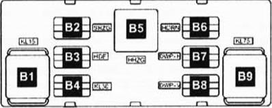
Description
| V1 | Terminal 15 power relay, (460) |
| V2 | Free |
| VZ | Free |
| B4 | Supply terminal courier 30, (449) |
| B5 | Heated rear window relay, (53) |
| B6 | Twin-horn courier, (449) |
| B7 | Washer pump double relay #1, (404) |
| B8 | Washer pump double relay #1, (404) |
| B9 | X terminal relay, (460) |
An additional relay holder is attached to the on-board power supply control unit. In vehicles with seat heating, this box is equipped with bimetallic thermal fuses for the heating elements.
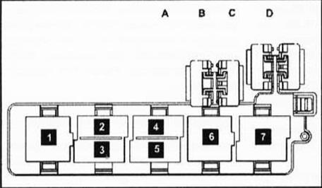
Description
- Auxiliary heater relay, (53)
- Free
- Fresh air blower relay, (404)
- Free
- Fuel Pump Relay #2, (404)
- Headlight washer relay, (53)
- Supply terminal relay 50, (433)
- A – Reserve
- B – Reservation
- C – Thermal fuse #1 (30 A) for driver’s seat adjustment
- D – Thermal fuse No. 2 (30 A) for driver’s seat adjustment
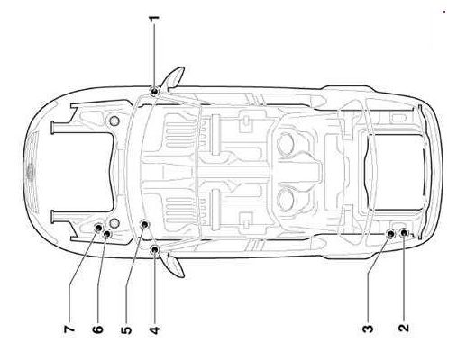
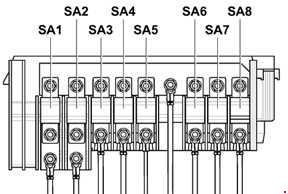
Trunk

Description
| 1 | 30A Fuse box left and right |
| 2 | 80A Fuses in the switching unit |
| 3 | 125A Switching unit power supply |
| 4 | 5A On-board power control unit |
There may be several relay components on the left side of the boot behind the side liner:
- 70A – Limousine;
- 60A – Variant.