Volkswagen Passat B5 (1996-2005) – fuse box diagram
Year of manufacture: 1996, 1997, 1998, 1999, 2000, 2001, 2002, 2003, 2004, 2005.
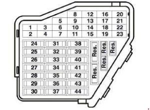
Lighter fuse (electrical outlet) in the Volkswagen Passat B5 (1996-2005). Is fuse 33 in the fuse box.
The fuse box is located on the left side of the passenger compartment
| Number | Amps [A] |
Description |
| 1 | 5 | Heated wash nozzle |
| 2 | 10 | Turning signal system |
| 3 | – | Not used |
| 4 | 5 | License plate illumination |
| 5 | 10 | Electric seats;
Air conditioning; Telematics; Multi-function steering wheel; Sunroof; Mirror adjustment; HomeLink. |
| 6 | 5 | Comfort Module System |
| 7 | 10 | ABS;
Cruise control system; Engine control unit. |
| 8 | 5 | Automatic Headlight Adjustment |
| 9 | 5 | Parking assistance |
| 10 | 5 | CD Switch;
Telematics; Multi-function steering wheel; Navigation; Radio. |
| 11 | 5 | Electric seats with memory |
| 12 | 10 | B+ (positive battery voltage)
for data link connector (DLC) |
| 13 | 10 | Brake lights |
| 14 | 10 | Comfort Module System |
| 15 | 10 | Instruments. cluster, air conditioning;
Automatic transmission. |
| 16 | 5 | ABS;
Steering angle sensor. |
| 17 | 10 15 |
Electrical outlet;
Telematics, |
| 18 | 10 | Right headlight, driving light |
| 19 | 10 | Left headlight, driving light |
| 20 | 15 | Right headlight, passing beam |
| 21 | 15 | Left headlight, dipped beam |
| 22 | 5 | Park light, right |
| 23 | 5 | Park light, left |
| 24 | 25 | Windshield wiper system |
| 25 | 30 | Fresh air blower;
Recirculation control; Air conditioning; Sunroof. |
| 26 | 30 | Rear window defogger |
| 27 | 15 | Rear window wiper system |
| 28 | 20 | Fuel Pump (FP) |
| 29 | 20 | Motor control unit,
Coolant fan. |
| 30 | 20 | Opening roof |
| 31 | 15 | Emergency Lights;
Cruise control system; Automatic transmission; Mirror adjustment; Diagnostics. |
| 32 | 20 | Engine Control Module (ECM);
Cruise control system. |
| 33 | 15 | Cigarette Lighter |
| 34 | 15 | Engine Control Module (ECM);
Injectors. |
| 35 | 30 | Trailer Socket |
| 36 | 15 | Fog Lights |
| 37 | 20 | Radio system, navigation |
| 38 | 15 | Comfort Module System |
| 39 | 15 | Emergency Lighting System |
| 40 | 25 | Double Horn |
| 41 | 25 | Telematics |
| 42 | 25 | ABS |
| 43 | 15 | Engine Control Module (ECM) |
| 44 | 30 | Heated seats |
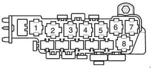
Arrangement of relays and fuses

| Relay arrangement in the thirteen panel
auxiliary relays above the relay panel |
||
| 1 | Cooling Fan Control (FC)-A/C
Relay (373) |
|
| 2 | Roof rack (79) | |
| 3 | Air conditioning clutch relay (267);
Air conditioning clutch relay (384). |
|
| 4 | Daytime Running Lights;
Server switching relay (173). |
|
| 5 | Cab alarm relay;
High beam relay; Emergency laser relay. |
|
| 6 | Lever Light Selector | |
| 7 | Light Fog Relay (381) | |
| 8 | Control module for multifunction steering wheel (451);
Control module for multifunction steering wheel (452). |
|
| 9 | Control module for multifunction steering wheel (451);
Control module for multifunction steering wheel (452). |
|
| 10 | Brake booster relay (373) | |
| 11 | Cab alarm relay;
Emergency laser relay (200). |
|
| 12 | Dual horn relay(53);
Cab alarm relay. |
|
| 13 | Park/Neutral(PNP) position;
Relay (175); Start relay position – clutch (53). |
|
| Fuses on the thirteenth
relay panel |
||
| A | 25 | Fuse for cabs |
| B | 20 | Fuse for cabs |
| B | 10 | Traffic lights on the left |
| C | 15 | Brake system fuse;
Vacuum pump. |
| D | 20 | Fuse in the power socket (12 V);
Rear console. |
| E | 5 | Fuse for cabs |
| E | 10 | Traffic lights on the right, |
| Position of relays in the relay panel | ||
| 1a | Dual horn relay(53) | |
| 2b | Load Reduction Relay (370) | |
| 3c | Not used | |
| 4d | Fuel pump relay (FP) (372) (409) | |
| V | Intermittent wiper blade (377) (389)
Intermittent windshield wiper stabilizer; Rain sensor (192). |
|
| VI | Intermittent windshield wiper (377) (389);
Intermittent windshield wiper stabilizer; Rain sensor (192). |
|
| Fuses in the relay panel | ||
| A | 20 | Fuse for 12V I-socket in the trunk |
| B | 20 | Fuse for 12V II socket in the trunk |
| C | 10 | Fuse for cabs |
Relay matrix on an eight-way auxiliary relay board behind the relay board
| Location of relays on the relay board | |
| 1 | Not used |
| 2 | Not used |
| 3 | Cooling fan control relay (FC) 80 W (373) |
| 4 | Not used |
| 5 | First speed cooling fan control relay (FC) (373) |
| 6 | Cooling fan control relay (FC) (373) |
| 7 | Pairing for ABS with ESP (373) |
| 8 | Cooling fan control relay (FC) (370) |
| Fuses in eighth panel
auxiliary relays |
|
| 30A | ABS hydraulic pump fuse |
| 30A | Power Window Fuse |
| 30A 40A 60A |
Cooling fan fuse |
| 5A | Cooling fan fuse |
| 30A 50A |
ABS hydraulic pump fuse |
| 30A | Circuit Breaker – Passenger Seat |
| 30A | Power socket switch – driver socket |
| 30A | Alarm system with burglar warning system;
Telematics. |
| 15A | Alarm system with burglar warning system |
Schematic of relays and fuses in the relay panel

| Number | Amps [A] |
Description |
| B | 10 | Fuses for injectors (S116) |
| B | 5 | Fuse for auxiliary engine (EC) coolant Pump |
| D | 50 | Fuse for secondary air pump (S130) |
| E | 40 | Fuse for thermal ignition coil (S115) |
| F | 5 | Engine Control Module (ECM) Fuses (S102) |
| G | 10 | Electronic motor fuse (S282) |
| 1 | Motronic Engine Control Module Power Supply Relay (167),
Engine code BDP |
|
| 2 | Secondary air pump relay (AIR) (373), (100) | |
| 3 | Motronic Engine Control Module Power Reay (429), (219)l
Additional auxiliary engine coolant (EC); Relay pump (53), (411) |
|