Volkswagen Caravelle – fuse box diagram
Year of manufacture: 2004, 2005, 2006, 2007, 2008, 2009, 2010, 2011, 2012, 2013 i 2014.
T6 from 2015
Cigarette lighter fuse (power socket) in the Volkswagen Caravelle Is fuse 12 in the fuse box in the passenger compartment.
The arrangement of the boxes in the Volkswagen Caravelle (Multivan) T5 and T6 is similar. However, their layout is different.
Location of the control units
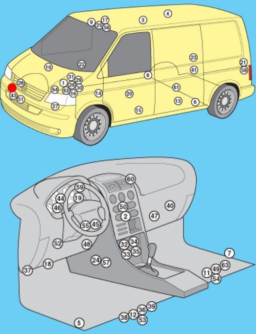
Description
| 1 | ABS electronic control unit |
| 2 | A/C Controller – on the heater control panel |
| 3 | Air conditioning controller (rear) – on the heater control panel |
| 4 | Antenna unit – if available |
| 5 | Driver’s side impact sensor |
| 6 | Side impact sensor, rear left |
| 7 | Passenger side impact sensor |
| 8 | Side impact sensor, rear right |
| 9 | Anti-theft control unit |
| 10 | Pickup system resonator |
| 11 | Audio output amplifier – under the right front seat – if equipped |
| 12 | Auxiliary battery 1 – under the front left seat – if equipped |
| 13 | Additional 2 (RV) mixer tap – in the kitchen cabinet |
| 14 | Additional heating control unit (Air Top 3500) – under the cabinet, right side – if present |
| 15 | Additional heating control unit (Thermo Tor) – under the cabinet, left side – if present |
| 16 | Battery pack |
| 17 | Camping Equipment Control Unit (RV) |
| 18 | Diagnostic connector (DLC) |
| 19 | Diagnostic unit – instrument panel |
| 20 | Driver’s door controller |
| 21 | Electric control for left rear door (with electric sliding door) – left pillar |
| 22 | Electric passenger door control unit |
| 23 | Right rear door wiring control unit (electric sliding doors) – right pillar |
| 24 | ESP stability control unit (includes acceleration sensor, lateral movement sensor) |
| 25 | Roof Lift Control Unit (RV) |
| 26 | ECM – close motor fuse / relay box 1 |
| 27 | Cooling fan motor control module 1 – suspension (front left) |
| 28 | Cooling fan motor controller 2 – on cooling fan motor 2 – if installed |
| 29 | Fuse / relay box, engine compartment 1 |
| 30 | Fuse / relay box, engine compartment 2 |
| 31 | Fuse / relay box, engine compartment Z |
| 32 | Fuse / relay box, instrument panel 1 – center instrument panel |
| 33 | Fuse / relay box 2, instrument panel – under instrument panel fuse / relay box 1 |
| 34 | Fuses / relay box, instrument cluster 3 – behind fuses / relay box, instrument cluster 1/2 |
| 35 | Fuse/relay box, instrument panel 4 – behind fuse/relay box, instrument panel 1/2 |
| 36 | Fuse / relay box, left seat – under the seat |
| 37 | Additional fuse 1 (differential lock switch, rear 10A) – front left pillar |
| 38 | Additional fuse 2 (additional heater 30A) – under the left-hand seat |
| 39 | Additional fuse 3 (left rear door electronics panel 40A) – under the left seat (some models) |
| 40 | Heater fan motor resistor 1 – near rear heater fan motor |
| 41 | Heating fan motor resistor 2 – near rear heater fan motor – if equipped |
| 42 | Beep tone 1 |
| 43 | Beep 2 – if available |
| 44 | Immobilizer control unit – instrument cluster |
| 45 | Immobilizer antenna ring – on ignition switch |
| 46 | Instrument cluster control unit – instrument panel |
| 47 | Telephone board – behind the glove box |
| 48 | Multi-function control unit 1 – functions: automatic transmission (automatic gearbox), charging system (with additional battery), cruise control, door/mask switch contact recognition, electric charge control, power windows, fuel pump, headlight washers, rear view mirror heater door view , rear window defroster, hazard warning lights, windshield defroster, horn, turn signals, instrument panel illumination, interior lights, automatic wipers, reverse lights, starter, sunroof, light switch, wiper |
| 49 | Multifunction control unit 2 – functions: anti-theft system, central locking, electrically operated side mirrors, power sliding doors, electrically operated windows, sunroof |
| 50 | Navigation control unit – on the navigation display |
| 51 | Room temperature sensor |
| 52 | Parking system control unit |
| 53 | Driver’s seat heating control unit |
| 54 | Heated passenger seat control unit |
| 55 | Steering wheel position sensor – if equipped |
| 56 | Electric roof control unit |
| 57 | SRS electronic control unit |
| 58 | Rear door open/close control – left “D” pillar – if equipped |
| 59 | Traffic information control unit – under the dashboard |
| 60 | Traffic information control unit (alternative position) – under the dashboard |
| 61 | Gearbox control unit (with 4-wheel drive) – rear final drive |
| 62 | Electronic gearbox control unit (automatic transmission) – in engine control unit |
| 63 | Voice synthesizer – under the right front seat – if equipped |
| 64 | Vehicle speed sensor – gearbox (some models) |
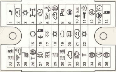
Engine compartment
Fuse mounting box
Description
| 1 | (5A) Cooling fan motor(s) |
| 2 | (5A) Coolant pump relay |
| 3 | (15A) Air Conditioning (5A) Crankcase Ventilation Resistor |
| 4 | (30A) Anti-lock braking system (ABS) or voltage stabilizer, stereo, radio |
| 5 | (15A) Automatic transmission |
| 6 | (30A) Anti-lock braking system (ABS) |
| 7 | (5A) Cooling fan motor control unit 1;
(7.5A) Washer pump. |
| 8 | (15A) Engine Management |
| 9 | (5A) Engine management, main ignition circuit relay |
| 10 | (5A) Engine management (15A) Load or exhaust valve |
| 11 | (5A) Power steering controller;
(30A) Headlight switch and relays. |
| 12 | (5A) Engine management;
(10A) Fuel pressure regulator. |
| 13 | (10A) Engine Management;
(10A) Xenon in the left headlight. |
| 14 | (5A) Engine management or fuel pump relay |
| 15 | (10A) Reversing light switch |
| 16 | (5A) Engine control or brake light switch, air flow meter |
| 17 | (5A) Anti-lock braking system (ABS) |
| 18 | (5A) Power steering |
| 19 | (5A) Brake light switch (brake pedal position sensor);
Clutch pedal position sensor. |
| 20 | (5A) Engine management |
| 21 | (5A) Exhaust gas recirculation valve |
| 22 | (10A) Engine management (injectors) |
| 23 | (25A) Automatic transmission;
(10A) Right xenon headlight. |
| 24 | (5A) Automatic transmission |
| 25 | (25A) Engine management, ignition |
| 26 | (25A) Engine management;
(5A) Left headlight. |
| 27 | (5A) Relay for cooling pump |
| 28 | (15A) High sound signal |
| 29 | (10A) Vehicle speed sensor;
(5A) Right headlight. |
| 30 | (15/20A) A/C/ additional heater pump relay, fuel pump, fuel pump relay |
| 31 | (15A) Engine management (lambda sensor) |
| 32 | (30A) Engine management (ignition);
(5A) Fuel pump relay. |
| 33 | (5A) Refrigerant pump relay motor control;
Glow plug. |
| 34 | (10A) Cooling fan motor control unit;
(5A) Bottle network control unit. |
| 35 | (10A) Engine Management;
(15A) Fuel level regulator. |
| 36 | (25A / 30A) Starter relay;
(5A) Data bus interface. |
High power fuse box
It is located next to the mount and is connected to the battery.
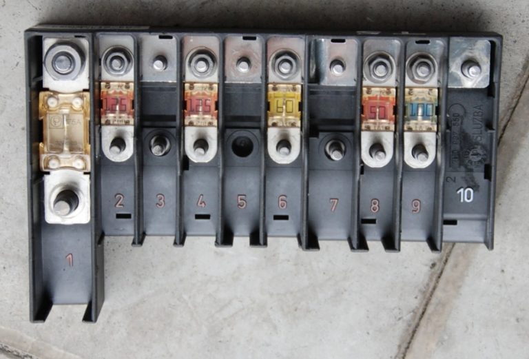
Description
| 1 | (175 / 225A) Generator |
| 2 | (125A) Battery power distribution;
Auxiliary ignition relay; Driver’s door controller; Passenger door controller; Rear window defroster; Terminal Relay X; Separate fuses. |
| 3 | (50A / 100A) Charging system (with additional battery);
Left rear door electric control unit (some models); Right tailgate electric control unit (some models); Relay – distributor in the charging system (with auxiliary battery). |
| 4 | (125A) Battery power distribution;
(70A) Positive connection in the engine compartment wiring harness. |
| 5 | (50A) Battery power distribution (some models), separate fuses |
| 6 | (60A) glow plug relay;
(50A) Exhaust air pump motor. |
| 7 | (70/80/100A) Cooling fan motor |
| 8 | (40/50/100A) Cooling fan motor, separate fuses |
| 9 | (100A) Battery power distribution;
Ignition switch. |
| 10 | – |
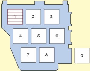
Relay Box
Also located next to the fuse box
Type 1

Description
| 1 | Electronic air conditioning control unit (manual temperature control) |
| 2 | Fuel pump relay 2 |
| 3 | Exhaust air pump relay |
| 4 | Relay for the main ignition circuits |
| 5 | Fuel pump relay 1 |
| 6 | A/C compressor solenoid clutch relay (automatic temperature control) |
| 7 | Automatic transmission control system relay |
| 8 | Power steering control unit |
| 9 | Coolant pump relay |
Type 2
Description
| 1 | Electronic air conditioning control unit (manual temperature control) |
| 2 | Fuel pump relay 2 |
| 3 | Exhaust air pump relay |
| 4 | Relay for the main ignition circuits |
| 5 | Fuel pump relay 1 |
| 6 | A/C compressor solenoid clutch relay (automatic temperature control) |
| 7 | – |
| 8 | Coolant pump relay |
| 9 | Start-up courier – if equipped |
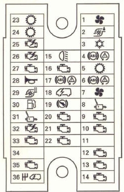
Passenger compartment
Main fuse box

Description
| 1 | (25A / 30A) Heater;
Air conditioner; Terminal 15 power relay. |
| 2 | (5A) Handwheel position sensor |
| 3 | (10A) Multifunction control unit 1 (on-board power supply) |
| 4 | (10A) Headlight range control;
(5A) Lane change assistant. |
| 5 | (15A) Left-Turn Light Bulb |
| 6 | (15A) Left-Turn Light Bulb |
| 7 | (15A) Multifunction control unit 1 (interior light or vehicle electrical system) |
| 8 | (5A) Diagnostic connector (DLC);
(15/20A) Controller for roof and sliding doors, rear door. |
| 9 | (15A) Brake light switch (brake pedal position sensor);
(30A) On-board power control unit. |
| 10 | (10A) Windshield wiper;
Rear wiper. |
| 11 | (5A) Number plate lamp |
| 12 | (15A) Lighter;
(5 / 30A) Light switch. |
| 13 | (5/10A) SRS electronic control unit |
| 14 | (30A) Additional heater;
Kimatization; (25A) Headlight switch. |
| 15 | (7.5) Air conditioning (switch and fan relay) |
| 16 | (5A) Multifunction control unit |
| 17 | (5A) Rear fog lamps, instrument cluster |
| 18 | (5A) Instrument cluster control module |
| 19 | (5A) Audio system;
Instrument cluster control unit; Multi-function control unit 1; Navigation system; Special equipment for vehicles. |
| 20 | (5A) Front left light;
Left brake light; Left rear light or differential lock. |
| 21 | (5A) Front light right;
Right brake light; Right taillight or starter relay; Engine control module. |
| 22 | (7.5 / 10A) Passenger airbag deactivation indicator;
Diagnostic connector (DLC); Instrument cluster control unit. |
| 23 | (5/30A) Starter relay (some models with manual transmission) |
| 24 | (5A) Handwheel position sensor |
| 25 | (7.5A) Air conditioning (fans) |
| 26 | (30A) Headlight switch |
| 27 | (15A) Right-Turn Light Bulb |
| 28 | (15A) High beam indicator, right headlight |
| 29 | (10A) Tailgate Signal Relay |
| 30 | (10A) Heated windshield washer nozzles;
Rear wiper motor. |
| 31 | (30A) Multifunction control unit 1 (horn) |
| 32 | (25/30A) Multifunction control unit 1 (wiper motor) |
| 33 | (15A) Audio system, navigation system, traffic information control module; |
| 34 | (25A) Automatic transmission control system;
Fuse / relay box, engine compartment 1. |
| 35 | (5A) Instrument lighting |
| 36 | (25A) Multifunction control unit 1 (turn indicators) |
Diagram of the lower section
Description
| 1 | (25A) Trailer electrical connector (15A) 10-pin connector |
| 2 | (5A) Anti-theft system |
| 3 | (5A) Additional air conditioning fan, left and right;
(10/15A) Optional equipment. |
| 4 | (10A) Control box control module (differential) |
| 5 | (10A) 6-pin accessory or connector |
| 6 | (5A) Engine oil level sensor (level, temperature) |
| 7 | (10A) Roof fan;
(30A) Anti-theft alarm. |
| 8 | (5A) Parking system |
| 9 | (5A) Steering column control module (cruise control) |
| 10 | (30A) Audio system;
(10A) Headlight range control, instrument lighting level. |
| 11 | (20A) Anti-theft alarm horn;
Multifunction control module 2; Electric sliding door; Rear door opening control module; (15A) Walkie-talkie; Anti-theft system. |
| 12 | (5A) Left headlight;
(10A) Brake light cut-off relay; (30A) On-board power control. |
| 13 | (5A) Cruise control master switch;
Multi-function control on steering wheel. |
| 14 | (5A) Telephone, right reflector;
(30A) On-board power management. |
| 15 | (5A) Automatic transmission or telephone and voice control |
| 16 | (5A) Navigation with audio system, telephone;
(7.5A) TV tuner. |
| 17 | (7.5A) Multifunction control unit (interior light, adjustable mirror) |
| 18 | (5A) Air Conditioning (some models) |
| 19 | (5A) Automatic dimming interior rear-view mirror |
| 20 | (10A) Multifunction control unit 1 (heating of side mirrors) |
| 21 | (5A) Anti-theft system or rain sensor |
| 22 | (5A) Air conditioning or pressure sensor |
| 23 | (5A) Auxiliary heater and accessories |
| 24 | (7.5A) Interior lamps |
| 25 | (15A / 25A) Heated seats |
| 26 | (10A) Tachograph (if equipped) |
| 27 | (15A) Fog lamps or power relay |
| 28 | (5A) Rear view mirror adjustment switch;
External mirror heaters. |
| 29 | (25A) Auxiliary heater |
| 30 | (5A) Auxiliary heater |
| 31 | (25A) Manhole;
(5A) Deck loader. |
| 32 | (20A) Headlight washers and their relay |
| 33 | (5A) Tachograph (if equipped) |
| 34 | (15A) Auxiliary power connector 3 (rear);
(5A) Steering wheel multifunction control module. |
| 35 | (10A) Multifunction control unit 1 (reversing light(s), with automatic transmission);
(20A) On-board power control unit. |
| 36 | (5A) Control unit for camping equipment, special equipment for vehicles |
Relay box behind the main fuse boxes
Type 1
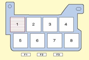
Description
| 1 | – |
| 2 | Relay 1 auxiliary heater |
| 3 | A/C fan motor relay, rear |
| 4 | Relay for auxiliary ignition circuits |
| 5 | – 06.03: Rotating warning relay (special purpose vehicle) |
| 6 | Brake Light Cut-Off Relay |
| 7 | Headlight Washer Pump Relay |
| 8 | A/C auxiliary pump/heater |
| F1 | – |
| F2 | (30A) Door control module (driver), door control module (passenger) |
| F3 | (40A) Heated Rear Window |
Type 2

Description
| 1 | Air conditioner fan motor relay, rear (some models) |
| 2 | Electronic steering column control unit |
| 3 | Electronic steering column control unit |
| 4 | Roof ventilation relay 1 |
| 5 | Differential lock control unit |
| 6 | 06/03: Tailgate Signal Relay |
| F1 | (15A) Siren (special purpose vehicle) |
| F2 | (10A) Siren (special purpose vehicle) |
| F3 | (10A) Rotating warning light (special vehicle) |
| F4 | (40A) Left-hand rear door control module (ECM) |
| F5 | (40A) 01/04: Right tailgate control module |
| F6 | (5A) 01/04: Voice synthesizer (if available) |
Box under the driver’s seat
Type 1

Description
| 1 | Relay – distributor in the charging system (with additional battery) |
| 2 | – |
| 3 | Relay – distributor in the charging system (with additional battery) |
| 4 | Special equipment for vehicles |
| 5 | Special equipment for vehicles |
| F1 | (5A) Control box for camping equipment |
| F2 | (10A) Accessory power socket 1 (front), refrigerator (RV) |
| F3 | (5A) Fresh Water Pump (camper) |
| F4 | (10A) Interior light, local lighting (commercial vehicle) |
| F5 | (30A) Body Power connector control module (commercial vehicle) |
| F6 | (40A) Roof Lift Control Module (Commercial Vehicle) |
| F7 | (5A) Antenna unit |
| F8 | (25A) Additional heater |
| F9 | (30A) Fan motor of heater air conditioner (automatic temperature control) |
| F10 | – |
| F11 | – |
| F12 | – |
| F13 | (40A) Right tailgate control module |
| F14 | (80A) Additional battery |
Type 2

Description
| 1 | – |
| 2 | Relay distributor in the charging system (with additional battery) |
| 3 | Special equipment for vehicles |
| 4 | Special equipment for vehicles |
| 5 | Special equipment for vehicles |
| F1 | (15A) Accessory power connector(s) |
| F2 | (15A) Accessory power connector (s) |
| F3 | (15A) Accessory power connector (s) |
| F4 | (15A) Refrigerator (RV), special equipment for vehicles |
| F5 | (5A) Antenna unit |
| F6 | (25A) Additional heater |
| F7 | (30A) Air conditioner/heating blower motor (automatic temperature control) |
| F8 | – |
| F9 | – |
| F10 | – |
| F11 | (40A) Right Rear Door Control Module |
| F12 | (80A) Additional battery |
Type 3

Description
- 5A – 10-pin connector / 6-pin connector
- 3A – 10-pin connector
- 5/15A – 10-pin connector or emergency data logger
- 15A – 10-pin connector
- 5A – 10-pin connector
- 25A – 6-pin connector
- Socket 15/30 – 12V, voltage converter
- 20 / 25A – Heater control unit (heater)
- 25 / 30A – Supply fan
- 15 / 30A – Air Conditioning
- 15A – Lighter
- 5A – 10-pin connector / 6-pin connector
- Local Relay
- Local Relays
- Local Relays
- 30A – Onboard Loader
- 30A – Hydraulic Roof Controller
- 10A – Lighting Boards
- 10A – Refrigerated Compartment
- 5A – Water Pump
- 5A – Camping Equipment Control Panel
- 15A – 12V Socket
- Socket 15A – 12V
- 10A – 12V roof fan or socket
- 15A – Trailer recognition control unit
- 20A – Trailer recognition control unit
- 20A – Trailer recognition control unit
- 7.5A – Trailer recognition control unit
- Reservation
- 5A – Voice Amplifier Control Unit
- Reservation
- Reservation
- 15A – Driver’s seat lumbar support
- 40A – Right Sliding Door Controller
- 80A – Control unit for charging the second battery
- 40A – Left Sliding Door Control Unit
- 40A – Supply Fan
- 6-pin connector
- Reservation
T6 caravel fuses
In the sixth generation, the main fuse holder is located under the glove box.