Volkswagen Caddy – Fuse diagram
Year of manufacture: 2010, 2011, 2012, 2013, 2014, 2015.
Cigarette lighter fuse (power socket) in Volkswagen Caddy Is fuse 20 or 47 in the fuse box in the instrument panel.
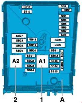
Location

- Fuses in fuse holder A -SA- (in electronics box, left side in engine compartment)
- Fuses in fuse holder B -SB- (left side in engine compartment)
- Fuses in fuse holder C -SC- (under the instrument panel on the left)
Fuse holder location A (A -SA-)

| Number |
Amps [A] |
Description |
||
| 1 | 150 | Alternator -C- | ||
| 200 | Alternator -C- 1) | |||
| 2 | 80 | Power steering controller -J500-;
Electromechanical power steering motor -V187-. |
||
| 3 | 50 | Radiator Fan Controller -J293- | ||
| 4 | 80 | Relay relay contact X -J59-
|
||
| 5 | 80 | Fuse holder C -SC- (-SC20- to -SC24- and -SC43- to -SC53-) | ||
| 6 | 40 | Thermal Low Power Relay -J359- | ||
| 7 | 80 | Thermal High Power Relay -J360- | ||
| 1) Models with 140 A generator only. | ||||
Location of the electronics box fuse holder (B -SB-).
| No. |
Amps [A] |
Description |
| 1 | – | – |
| 2 | 30 | Mechatronic unit for double-clutch transmission -J743- |
| 3 | 5 | Battery monitoring control unit -J367-;
On-board power control unit -J519- (T52a / 24). |
| 4 | 20 | ABS control unit -J104-;
ABS hydraulic unit -N55-. |
| 5 | 15 | Mechatronic unit for double-clutch transmission -J743- |
| 6 | 5 | Control unit in instrument panel -J285-;
Electronic steering column control unit -J527-. |
| 7 | 40 | Terminal 15 supply voltage relay -J329-;
Fuse holder C -SC- (-SC9- to -SC16- and -SC25- to -SC27-). |
| 8 | 15 | Control unit with display for radio and navigation -J503-;
Radio -R-; Voltage Stabilizer -J532- 3) ; Control module with display for radio and navigation system -J503-; Fuse 57 in fuse holder C -SC57-; Fuse 58 in fuse holder C -SC58-. |
| 9 | 5 | Electronic control unit for cell phones -J412-4 ) |
| 10 | 5 | Main Courier -J271-;
Engine control unit -J623-; Motor element current supply relay -J757-. |
| 11 | 30 | Auxiliary heater control unit -J364- |
| 12 | 5 | Data bus diagnostic interface -J533- |
| 13 | 15 | Engine control unit -J623- (gasoline engine) |
| 30 | Engine control unit -J623- (diesel engine) | |
| 14 | 15 | Fuel pressure control valve -N276- (diesel engine);
Fuel metering valve -N290- (diesel engine). |
| 20 | Ignition transformer -N152-;
Ignition coil 1 with output stage -N70-; Ignition coil 2 with output stage -N127-; Ignition coil 3 with output stage -N291-; Ignition coil 4 with output stage -N292-. |
|
| 15 | 5 | Low thermal power relay -J359- (diesel engine);
High thermal power relay -J360- (diesel engine); Fuel pump relay -N17-; Electric fuel pump 2 relay -J49-; Automatic light period control unit -J179-. |
| 10 | Lambda probe heater -Z19-;
Lambda probe heater 1 after catalytic converter -Z29-; Low heat output relay -J359-; High heat output relay -J360-; Fuel pump cut-off relay -J333-. 2) ; Gas injection valve 1 -N366- 1) ; Gas injection valve 2 -N367- 1) ; Gas injection valve 3 -N368-1 ) ; Gas injection valve 4 -N369-1 ) . |
|
| 15 | High pressure valve for gas mode -N372- 2)
Gas tank valve -N495- 2) Gas level sensor -G707- 2) Gas injection valve 1 -N366-2 ) Gas injection valve 2 -N367- 2) Gas injection valve 3 -N368-. 2) Gas injection valve 4 -N369-2 ) |
|
| 16 | 30 | On-board power control unit -J519- (T52c / 42);
Right fog lamp -L23-; Right corner fog lamp -L149-; Rear left fog lamp -L46-; Rear right fog lamp -L47-; Right operating daytime running lamp -L175-; Left side operating lamp -M1-; Right rear light bulb -M2-; Left rear indicator lamp -M6-; Front right indicator lamp -M7-; Left brake lamp -M9-; Right reversing lamp -M17-; Left indicator amplifier lamp -M18-; Height-mounted brake lamp -M25-; Right cross beam light bulb -M31-; Right high beam lamp -M32-; |
| 17 | 15 | Horn relay -J413- |
| 18 | 30 | Special vehicle control unit -J608- |
| 19 | 30 | Wiper motor control unit -J400- |
| 20 | 10 | Fuel tank shut-off valve 1 -N361- 1)
Fuel tank shut-off valve 2 -N362-1 ) Fuel tank shut-off valve 3 -N363-1 ) Fuel tank shut-off valve 4 -N429-1 ) Fuel tank shut-off valve 5 -N430-. 1) Coolant circulation pump -V50- |
| 21 | 10 | Lambda probe heater -Z19- (diesel engine) |
| 15 | Fuel pump controller -J538-;
Lambda probe heater -Z19-; Lambda probe heater 1 after catalytic converter -Z29-. |
|
| 22 | 5 | Clutch position transmitter -G476-;
Brake light switch -F-. 5) |
| 23 | 5 | Additional cooling pump relay -J496- |
| 10 | Air flow meter -G70- (diesel engine)
Charge pressure control solenoid valve -N75- (diesel engine) Exhaust gas recirculation radiator switching valve -N345- (diesel engine) Control unit for gas mode -J659-. Gas shut-off valve relay -J908- 1) High pressure valve for gas mode -N372-1 ) |
|
| 15 | Fuel pressure control valve -N276- | |
| 24 | 10 | Radiator Fan Control Unit -J293-
Secondary air pump relay -J299- Secondary Coolant Pump Relay -J496- Activated carbon filter solenoid valve 1 -N80- Coolant control valve -N515-. Intake manifold bypass valve with variable height -N156-. Coolant circulation pump 2 -V178-. Injector, cylinder 1 -N30-. 1) Injector, cylinder 2 -N31- 1) Injector, cylinder 3 -N32- 1) Injector, cylinder 4 -N33- 1) |
| 25 | 40 | ABS Hydraulic Pump -V64-;
ABS control unit -J104-. |
| 26 | 30 | On-board power control unit -J519- (T52a / 1);
Left corner illumination lamp -L148-; Left fog lamp -L22-; Rear left fog lamp -L46-; Right rear fog lamp -L47-; Daytime running light bulb left -L174-; Right side lamp -M3-; Left rear light bulb -M4-; Left front indicator lamp -M5-; Rear right indicator lamp -M8-; Right hand brake lamp -M10-; Left hand reversing lamp -M16-; Right bulb indicator amplifier -M19-; Left dipped-beam lamp -M29-; Left-hand high beam lamp -M30-. |
| 27 | 40 | Secondary air pump motor -V101- |
| 50 | Automatic light period control unit -J179- | |
| 28 | – | – |
| 29 | 30 | Fuse 18 in fuse holder C -SC18-;
Fuse 19 in fuse holder C -SC19-. |
| 50 | Fuse 35 in fuse holder C -SC35-;
Fuse 39 in fuse holder C -SC39-; Fuse 54 in fuse holder C -SC54-; Fuse 55 in fuse holder C -SC55-; Fuse 59 in fuse holder C -SC59-; Fuse 60 in fuse holder C -SC60-. |
|
| 30 | 50 | Fuse holder C -SC- (-SC40- to -SC42-) |
| 1) only for vehicles with engine code BSX (2) only for vehicles with engine code CHGA (3) only for vehicles with a start/stop system 4) only for vehicles without a start/stop system 5) valid as of November 2011 |
||
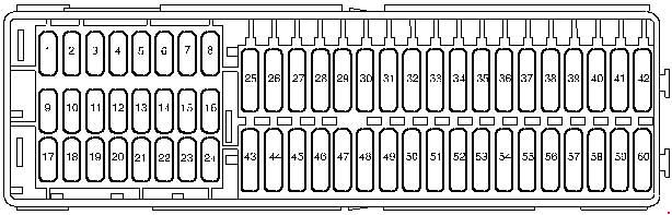
Positions of the fuses in the fuse holder C -SC-.
| Number |
Amps [A] |
Description |
| 1 | – | – |
| 2 | – | – |
| 3 | – | – |
| 4 | – | – |
| 5 | – | – |
| 6 | – | – |
| 7 | – | – |
| 8 | – | – |
| 9 | 10 | -Special vehicles…
4-pin connector -T4aa- Pin 1 3) ; 10-pin -T10l-, Contact 4 (interface for special functions). |
| 10 | 5 | Fuel pump relay -J17-;
Main Relay -J271-; Gas mode control unit -J659-; Terminal 50 power relay -J682-; Starter relay 1 -J906-; Voltage stabilizer -J532-; Data bus diagnostic interface -J533-; Motor control unit -J623-. |
| 11 | 5 | Parking assistance control unit -J446-;
Parking assist control unit -J791-. |
| 12 | 5 | -Special vehicles…
Taximeter -G41-; Taximeter mirror -G511-. |
| 10 3) | -Special vehicles… 3)
2-pin connector -T2ab-, Contact 1; 2-pin connector -T2ac-, Contact 1; 28-pin connector -T28b-, Contact 13. |
|
| 20 4) | -Special vehicles… 4)
8-pin connector -T8k-, Pin 8; 28-pin connector -T28a-, Pin 20; 28-pin connector -T28b-, Pin 20. |
|
| 13 | 7.5 | Brake light switch -F- 3) ;
Light range regulator -E102-; TCS and ESP button -E256-; Tire pressure indication button -E492-; Start / stop button -E693-; ABS control unit -J104-; Trailer detector control unit -J345-; Four-wheel drive control unit -J492-; Power steering controller -J500-; Gear lever sensor controller -J587-; Mechatronic module for dual-clutch transmission -J743-; Left headlight range control motor -V48-; Right headlight range control motor -V49-; Control unit for cornering light and headlight range control -J745-. |
| 14 | 10 | Reversing light switch -F4-;
Air flow meter -G70-; Additional heater operation relay -J485-; Control unit on instrument panel -J285-; Crankcase ventilation heating element -N79-; Activated carbon filter solenoid valve 1 -N80-; Diagnostic connector -U31-; 16-pin connector -T16-, Pin 1. |
| 15 | 5 | Airbag control unit -J234-;
Passenger side airbag deactivation warning light -K145-. |
| 16 | 5 | Light switch -E1-;
Heater/heat output switch -E16-; High pressure transmitter -G65-; Air quality sensor -G238-; Oil level and temperature sensor -G266-; Automatic anti-glare interior mirror -Y7-. |
| 17 | – | – |
| 18 | 10 | -Special vehicles…
Warning; Cab pilot control unit -J601-. |
| 10 | -Special vehicles…
10-pin socket -T10l- contact 6 (interface for special functions) |
|
| 19 | 10 | -Special vehicles…
Taximeter -G41-; Taximeter mirror -G511-; Cab remote control panel -J601-; Two-way radio communication -R8-; Printers -R98-. |
| 10 | -Special vehicles…
10-pin socket -T10l-, pin 7 (interface for special functions) |
|
| 20 | 20 | Cigarette Lighter -U1- 7) |
| 21 | 10 | Light switch -E1-;
Heating/heat switch -E16-; Rain and light sensor -G397-; Rear window heating relay -J9-; Climate controller -J255-; Air conditioning system controller -J301-; Horn relay -J413-; Auxiliary pilot receiver coolant heater -R149-; Shift lever sensor controller -J587-; -U31- diagnostic connector; 16-pin connector -T16-, Pin 16; Interior lighting switch -E599- (Camper); Rear interior lighting switch -W43- (Camper). |
| 22 | 10 | On-board power control unit -J519- (T52b / 42) 2) |
| 23 | 5 | -Special vehicles…
Interior light switch (cab) -E115-; Cab shift signal -E138-; 10-pin -T10l- Pin 1 (interface for special functions). |
| 10 | -Special vehicles…
3-pin connector -T3ak- Pin 1 3) Flashing Light Relay -J630- 4) |
|
| 24 | 5 | Interior monitoring sensor -G273-;
Vehicle tilt transmitter -G384-; Anti-theft alarm sensor -G578-; Beep -H12-; On-board power control unit -J519- (T52c / 1). |
| 25 | 10 | Output module for left headlight -J667- |
| 26 | 10 | Output module for right side reflector -J668- |
| 27 | – | – |
| 28 | 20 | 12 V socket 3 -U19-, in the glove box. |
| 29 | 15 | Rear wiper motor -V12- |
| 30 | – | – |
| 31 | 5 | Heater/heat output switch -E16-;
Left wash nozzle heating element -Z20-; Right wash nozzle heating element -Z21-. |
| 32 | – | – |
| 33 | 40 | Air conditioning system control unit -J301-;
Heating/heat switch -E16-. |
| 34 | – | – |
| 35 | 10 | -Special vehicles… 3)
Fluorescent light at the back of the high roof -W41-; Fluorescent light in the middle of the high roof -W42-. |
| 36 | – | – |
| 37 | – | – |
| 38 | – | – |
| 39 | 20 | -Special vehicles…
10-pin socket -T10ai- Pin 1 3) |
| 30 | -Special vehicles…
4-pin connector -T4ad-, Pin 1 4) |
|
| 40 | 20 | Trailer detector control unit -J345- |
| 41 | 20 | Trailer detector control unit -J345- |
| 42 | 20 | Trailer detector control unit -J345- |
| 43 | 15 | Fuel pump relay -J17-;
Electric fuel pump 2 relay -J49-; Additional fuel pump -V393-. |
| 44 | 40 | Fresh air fan controller -J126-;
Fresh air fan control -V2-. |
| 45 | 20 | Headlight washer relay system -J39-;
Headlight washer system pump -V11-. |
| 46 | 10 | On-board power control unit -J519- (T52b / 42) 1) ;
Interior front lighting -W1-; Luggage compartment lighting -W3-; Glove box illumination -W6-; Rear interior lighting -W43-. |
| 30 | Driver’s door controller -J386-2 ) | |
| 47 | 30 | Cigarette Lighter -U1- 6)
Contact release relay X -J59- 7) 8) Fuse holder C -SC- (-SC28- to -SC33-) 7) 8) |
| 48 | 30 | Controller for heated front seats -J774- |
| 49 | 30 | Driver’s Door Controller -J386- 1)
Front passenger door controller -J387- |
| 50 | 20 | On-board power control unit -J519- (T52b / 1);
Rear wiper motor -V12-; Windshield washer pump and rear window washer pump -V59-; Washer pump -V5-. |
| 51 | 15 | Trailer power relay -J941-;
Trailer power socket -U10- (T13 / 10). |
| 30 | – Special Vehicles
– 10-pin connector -T10ai-, Contact 4; 10-pin connector -T10ai-, Contact 5. |
|
| 52 | 25 | Heated rear window relay -J9-;
Heated rear window -Z1-; Heated rear window in left door -Z26-; Heated rear window on right door -Z27-; Fresh air blower relay -J13-; Fresh air blower series resistor with overheat fuse -N24-; Fresh air blower -V2-. |
| 53 | 15 6)
20 7) |
12 V socket -U5-, in the rear center console;
12 V socket 2 -U18-, In the rear left side panel. |
| 54 | 15 | -Special vehicles… 4)
Switching relay 1 for ceiling fan -J180-. |
| 55 | 15 | -Special vehicles… 4)
8-pin connector -T8m-, Contact 4; 8-pin connector -T8n-, Contact 4. |
| 56 | – | – |
| 57 | 5 | Dashboard control unit -J285-5 )
Electronic steering column control unit -J527-5 ) |
| 58 | 5 | Electronic control unit for cell phones -J412-5 ) |
| 59 | 5 | -Special vehicles…
Radio switch -E72- Ignition bypass button -E489- Daytime running light off button -E652- Accident data memory -J754- |
| 60 | 30 | – Special Vehicles –
3-pin connector -T3al-, Contact 1. |
| 1) before April 2011 2) after May 2011 3) before October 2011 4) after November 2011 5) only for vehicles with start-stop system 6) before October 2012 7) after November 2012 8) only for vehicles with Climatronic |
||