Volkswagen Arteon (2017-2019) fuses and relays
The Volkswagen Arteon is a car that has been in production since 2017. It belongs to the upper middle class (segment E). The Arteon is the successor to the CC model. Thus, it is the flagship product of the Wolfsburg-based company. The name is not a coincidence either, it is a conglomeration of words Art e eon, meaning art and a reference to Phideon (a VW model available on the Chinese market).
Year of production: 2017, 2018, 2019.
Lighter fuse (electrical outlet) in the Volkswagen Arteon (2017-2019). Is fuse 12 in the fuse box
Passenger compartment fuse box
Fuse box location
Steering wheel with Left:
The fuse holder is located behind the glove box on the left side of the instrument panel.
Steering wheel on the right side:
The fuse holder is located behind the cover on the left side of the glove box.
Diagram of the fuse box

Fuse and relay assignment in the passenger compartment
| Number | Amps [A] | Description |
|---|---|---|
| 1 | 30A | Heater control unit with reducing agent -J891-. |
| 2 | 10 A | Electronic steering column control unit -J527- |
| 3 | – | – |
| 4 | 7,5 A/
10 A. |
Alarm Horn -H12-. |
| 5 | 5A /
7,5A |
Data bus diagnostic interface -J533- |
| 6 | 5A/
7,5A |
Gear Shift Lever -E313- |
| 7 | 10 A | Heating and air conditioning control -EX21-;
Rear air conditioning control and display unit -E265-; Remote control receiver for auxiliary refrigerant heater -R149-; Relay rear window heater -J9-; Analog clock -Y-; Tire pressure monitoring system control unit -J502-. |
| 8 | 7,5 A /
10 A. |
Rotary light switch -EX1-;
Electromechanical parking brake button -E538-; Rain and light sensor -G397-; Diagnostic connector -U31-; Anti-theft alarm sensor -G578-; Backlighting on the left -L181-; Backlighting on the right -L182-; Interior front illumination -WX1-; Anti-theft alarm sensor -G578-; Control unit for controlling the range of corners and headlights -J745-; Light for left front door contour illumination -L251-; Light for left rear door outline light -L253-; Light for right front door marker light -L252-; Light for right rear door marker light -L254-. |
| 9 | 5A /
7,5A |
Electronic steering column control unit -J527- |
| 10 | 7,5 A /
10 A. |
Front information display unit i
Operating unit control unit -J685-; Head-up display control unit -J898-. |
| 11 | 40A | On-board power control unit -J519-. |
| 12 | 20A | Control unit 1 for information electronics -J794-;
Control unit for navigation system -J856-1). |
| 13 | 25A | Front Left Seat Belt -NX10- |
| 14 | 40A | Fresh Air Fan Control Unit -J126- |
| 15 | 10 A | Control unit for electronic steering column lock -J764- |
| 16 | 7,5A | Bi-directional signal amplifier for mobile/service phones
data transmission -J984- USB charging socket 1 -U37- Storage compartment with cell phone interface -R265- USB hub -R293- |
| 17 | 7,5A | Instrument panel insert -KX2-;
Emergency call module control unit and communication unit -J949-. |
| 18 | 7,5A | Control unit for the upper chamber -J928-;
Back cover bracket -EX37-; Rear top camera -R246-. |
| 19 | 7,5A | Interface with the input and commissioning system -J965- |
| 20 | 7,5 A /
10 A / 15 A. |
Relay agent dosing system -J963-;
Vacuum pump relay -J318-. |
| 21 | 15A | Four-wheel drive control unit -J492- |
| 22 | 15A | Trailer detector control unit -J345- |
| 23 | 20A /
30A |
Sliding roof adjustment control unit -J245- |
| 24 | 40A | On-board power control unit -J519-. |
| 25 | 30A | Driver’s Door Controller -J386-
Driver’s tailgate control unit -J926- |
| 26 | 30A | On-board Power Control Unit -J519- |
| 27 | 30A | On-board Power Control Unit -J519- |
| 28 | 25A | Trailer detector control unit -J345- |
| 29 | 5A | Remote start system relay -J471- |
| 30 | 10 A | Remote start system relay -J471- |
| 31 | 30A | Back Cover Controller -J605- |
| 32 | 10 A | Front camera for driver assistance systems -R242-;
Adaptive cruise control -J428-; Park assist control unit -J446-; Lane change assist control unit -J769-; Lane change assist control unit 2 -J770-. |
| 33 | 5A /
7,5A |
Airbag control unit -J234- |
| 34 | 7,5A | Interior mirror -EX5-
Power socket relay -J807- Reversing light switch -F4- Cooling circuit pressure sensor -G805- Air quality sensor -G238- Instrument panel center switch module -EX22- Center switch module 1 in center console -EX23- Material sound control unit -J869- Pushbutton for electromechanical parking brake -E538- |
| 35 | 7,5 /
10A |
Diagnostic connection -U31- |
| 36 | 5A /
7,5A |
Headlight front right -MX2- |
| 37 | 5A /
7,5A |
Front left reflector -MX1- |
| 38 | 25A | Trailer detector control unit -J345- |
| 39 | 30A | Front Passenger Door Controller -J387-
Rear passenger side door controller -J927- |
| 40 | 20A | 12 V Socket -U5-
12 V socket 2 -U18- 12 V socket 3 -U19- |
| 41 | 25A | Right Front Seat Belt -NX11- |
| 42 | 40A | On-board power control unit -J519-. |
| 43 | 40A | Digital Audio Package Control Unit -J525- |
| 44 | 15A | Trailer detector control unit -J345- |
| 45 | 15A | Driver’s seat adjustment control unit -J810-
Front Left Seat Fan 1 -V514- Left front seat backrest fan 1 -V512- |
| 46 | 30A | DC/AC converter with socket, 12 V – 230 V -U13-. |
| 47 | – | – |
| 48 | – | – |
| 49 | 5A /
7,5A |
Clutch position transmitter -G476-.
Start relay 1 -J906- Start Relay 2 -J907- |
| 50 | 40A | Rear Door Controller -J605- |
| 51 | 25A | Rear air conditioning system control and display unit -E265- |
| 52 | 15A | Electronically controlled damping control unit -J250-. |
| 53 | 30A | Heated Rear Window Relay -J9- |
| Relay: | ||
| R1 | Reducing agent dosing system relay -J963- | |
| R2 | – | |
| R3 | – | |
| R4 | Terminal 15 supply voltage relay -J329- | |
| R5 | Heated Rear Window Relay -J9- | |
| R6 | Relay for sockets -J807- |
The fuse box holder also contains the following fuses:
| Number | Amps [A] | Description |
|---|---|---|
| A | 15A | Control unit for adjustment
right front seat -EX34-; Front cushion fan right seat 1 -V518-; Front backrest fan right seat 1 -V516-; |
| B | 5A | Remote start system relay -J471- |
| C | 7,5A | USB charging socket 1 -U37- |
| R1 | Remote start system relay -J471- |
Engine compartment fuse box
Fuse box diagram
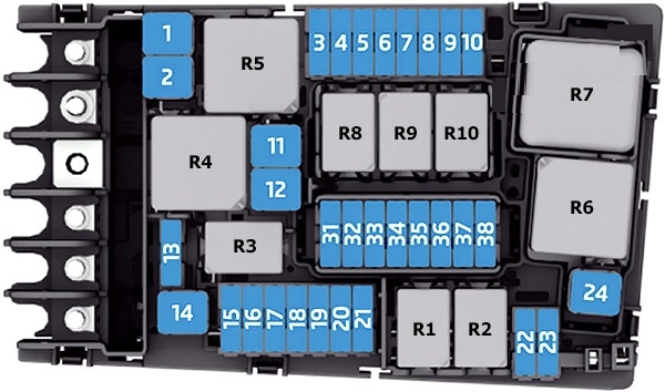
Assignment of fuses and relays in the engine compartment
| Number | Amps [A] | Description |
|---|---|---|
| 1 | 25A | ABS control unit -J104- |
| 2 | 40A /
60A |
ABS control unit -J104-;
ABS hydraulic pump -V64-. |
| 3 | 15A 30A |
Motor Controller -J623- |
| 4 | 5A /
7,5A / 10A |
Radiator Fan -VX57-
High thermal power relay -J360- Low Thermal Power Relay -J359- Oil pressure control valve -N428-. Turbocharger air recirculation valve -N249- Intake manifold flap valve -N316- Piston cooling nozzle control valve -N522-. Oil level and temperature sensor -G266- Turbine diverter valve -N529- Engine component power supply relay -J757- |
| 5 | 10 A | Fuel pressure control valve -N276-
Fuel metering valve -N290- Engine component current supply relay -J757-. Turbine diverter valve -N529- |
| 6 | 5A /
7,5A |
Brake light switch -F- |
| 7 | 7,5 A /
10 A / 15 A. |
Charge air cooling pump -V188-.
Transmission cooling valve -N488- Coolant shutoff valve -N82- Additional pump for heating -V488-. Cylinder head cooling valve -N489-. Oil pressure control valve -N428- Leak detection in the fuel tank controller -J909- |
| 8 | 15A | Lambda probe 1 before catalytic converter -GX10-
Lambda probe 1 after catalytic converter -GX7- Control unit for NOx transmitter -GX30- Control unit for NOx transmitter 2 -J881- |
| 9 | 5A /
10A |
Exhaust Flap Controller -J883-
Exhaust flap controller 2 -J945- Automatic light period control unit -J179- Crankcase breather heating element -N79- Air mass flow meter -G70- Auxiliary heating pump -V488-. Activated carbon filter solenoid valve 1 -N80-. Exhaust camshaft control valve 1 -N318-. Camshaft control valve 1 -N205- |
| 10 | 15A / 20A | Fuel pump control unit -J538- |
| 11 | 40A / 50A | Auxiliary Air Heating Element -Z35- |
| 12 | 40A | Auxiliary Air Heating Element -Z35- |
| 13 | 30A | Auxiliary hydraulic pump 1 for gearbox oil -V475-. |
| 14 | 40A | Heated windscreen relay -J47- |
| 15 | 15A | Horn Relay -J413- |
| 16 | 20A | Motor element power supply relay -J757- |
| 17 | 7,5A | Motor control unit -J623-;
ABS control unit -J104-; Heated windshield relay -J47-. |
| 18 | 5A / 7.5A | Battery monitor control unit -J367-;
Data bus diagnostic interface -J533-. |
| 19 | 30A | Wiper motor control unit -J400- |
| 20 | 10 A | Alarm horn -H12- |
| 21 | 30A | Heated Windscreen Relay 2 -J611- |
| 22 | 5A / 7.5A | Motor Controller -J623- |
| 23 | 30A | Starter -B- |
| 24 | 40A | Auxiliary Air Heating Element -Z35- |
| 31 | – | – |
| 32 | – | – |
| 33 | 30A | Heated windscreen relay 2 -J611- |
| 34 | 30A | Heated windscreen relay 2 -J611- |
| 35 | 30A | Wiper Motor Control Unit -J400- |
| 36 | – | – |
| 37 | 30A | Auxiliary heater control unit -J364- |
| 38 | – | – |
| Relay: | ||
| R1 | Start Relay 1 -J906- | |
| R2 | Start Relay 2 -J907- | |
| R3 | Horn relay -J413- | |
| R4 | High thermal power relay -J360- | |
| R5 | main relay -J271- (gasoline);
Terminal 30 supply voltage relay -J317- (Diesel). |
|
| R6 | Automatic light period control unit -J179- (gasoline). | |
| R7 | Thermal Low Power Relay -J359- (diesel) | |
| R8 | Current supply relay for motor components -J757-.
(2.0 l gasoline engine) |
|
| R9 | Heated windscreen relay -J47- | |
| R10 | Heated windscreen relay 2 -J611- |