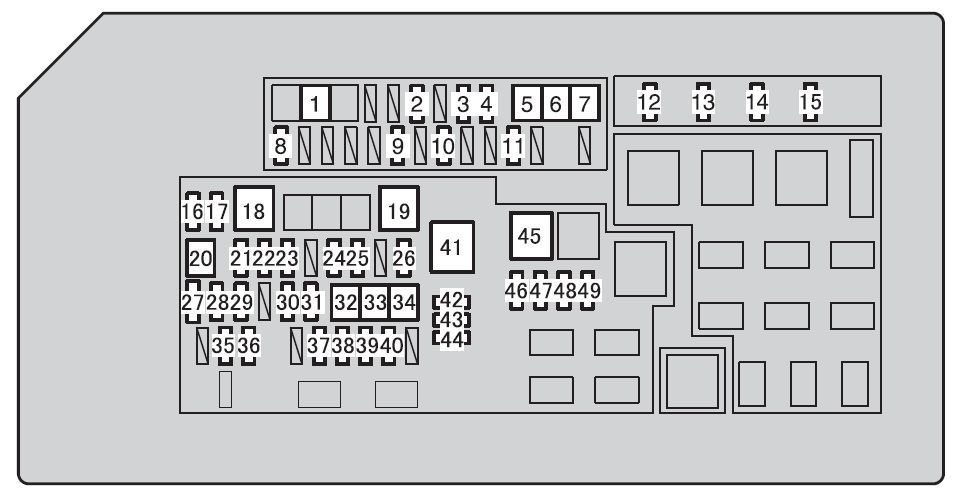
Fuse and relay box diagram – Toyota Tacoma
Applies to new vehicles in years:
2001, 2002, 2003, 2004.
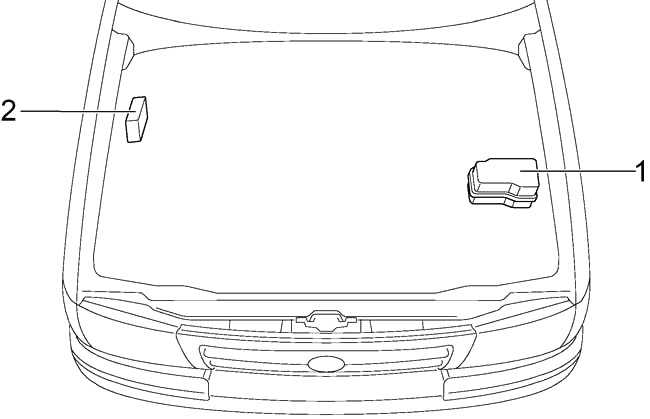
Passenger compartment
- Circuit breaker relay
- ECU Body
- ECU Rear Differential Lock
- Fuse box
- J/B
- Air conditioning control unit
- J/B
- Daytime running light relay №4
- Motor control module
- Gearbox control relay
- Cruise control ECU
- 4WD ECU (2-4 select SW) / ECU O/D (2RZ-FE with A/T)
- Gear Shift Control Relay
- Daytime Running Light Relay (main)
- Center airbag sensor assembly
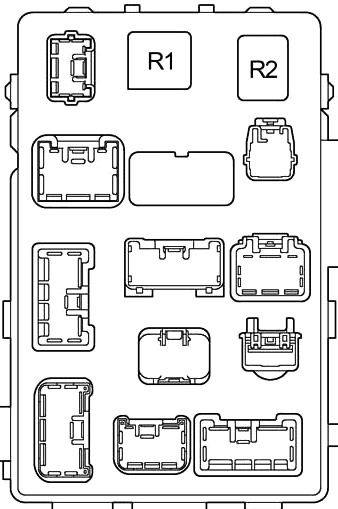
Diagram of the fuse box in the passenger compartment
The fuse panel is located behind the cover on the instrument panel on the driver’s side.
Rear:
| Number | Amps [A] | Description |
| 1 | – | – |
| 2 | 15 | Cigarette lighter, clock, electric mirrors, reversing lights, automatic gear locking, SRS airbag system, tensioners seat belts, car audio system |
| 3 | 15 | Cruise control system, anti-lock braking system, automatic gear shifting lock system, SRS airbag system |
| 4 | 10 | Daytime running light system, reversing lights, cruise control, rear differential lock, electronically controlled automatic transmission, starting system, charging system, air conditioning system |
| 5 | 7,5 | SRS warning light, air conditioning system |
| 6 | 10 | Direction indicators, emergency flashers |
| 7 | 7,5 | Gauges and indicators, SRS airbag system, tensioners seat belts, multipoint fuel injection system/sequential multipoint fuel injection system |
| 8 | 15 | Emergency lights, horns |
| 9 | 20 | Windshield wipers and washers |
| 10 | – | – |
| 11 | 7,5 | Clutch start override system, starting system |
| 12 | 20 | ADD control system, four-wheel drive control system, rear differential lock system |
| 13 | – | – |
| 14 | 10 | Stop lights, height-mounted stop light, cruise control, anti-lock braking system, multipoint fuel injection system/sequential multipoint fuel injection system |
| 15 | 30 | Electric windows, electric seat |
| Relay | ||
| R1 | Blinker | |
| R2 | Power relay (electric windows, electric seat ) | |
Engine compartment
- Fuse box
- ABS actuator with ECU
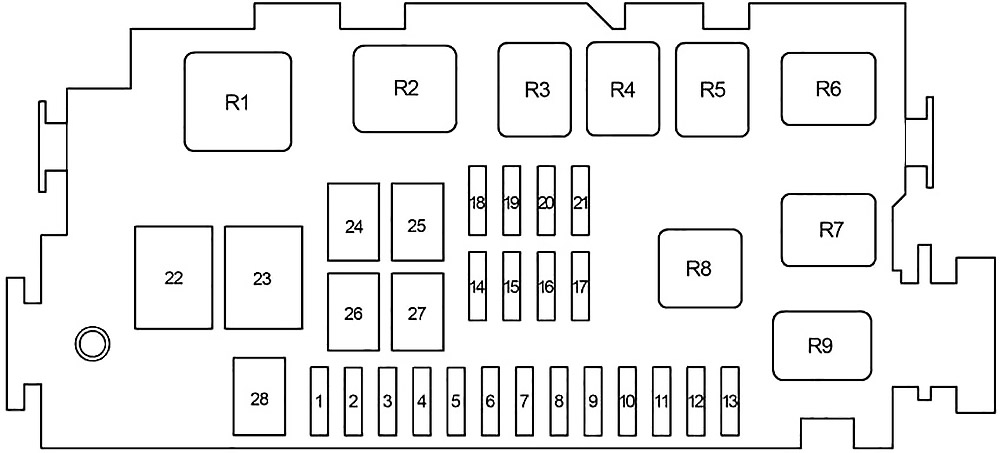
Diagram of the fuse box in the engine compartment
| Number | Amps [A] | Description |
| 1 | 7,5 | Daytime running light system |
| 2 | 10 | Right headlight |
| 10 | with DRL: Headlight right (high beam), Headlight indicator light | |
| 3 | 10 | Left Headlight |
| 10 | with DRL: left headlight (high beam) | |
| 4 | 10 | with DRL: Headlight right (low beam) |
| 5 | 10 | with DRL: Left headlight (low beam) |
| 6 | 10 | Tail lights, license plate light |
| 7 | – | – |
| 8 | 10 | Air conditioning system |
| 9 | – | – |
| 10 | – | – |
| 11 | – | – |
| 12 | – | – |
| 13 | – | – |
| 14 | 15 | Multi-port fuel injection system/ sequential multi-point fuel injection system |
| 15 | Fog Lights | |
| 15 | 15 | Car audio system, interior lighting, clock, personal lighting, exterior door lights, daytime running light system, indicators and gauges |
| 16 | 7,5 | On-board diagnostic system |
| 17 | 20 | Multi-port fuel injection system/ sequential multi-point fuel injection system |
| 18 | 7,5 | Charging system |
| 19 | 15 | Power socket |
| 20 | – | – |
| 21 | – | – |
| 22 | 60 | Anti-lock braking system, traction control system, “AUTO LSD” system, vehicle stability control system |
| 23 | 120 | All elements of the “AM1”, “HEATER”, “AC”, “TAIL”, “ALT-S” and “PWR OUTLET” fuses. |
| 24 | 50 | All fuse components “AC |
| 25 | 40 | Starting system |
| 26 | 50 | All components of the “POWER”, “HORN-HAZ”, “STOP” and “ECU-B” fuses. |
| 27 | 30 | Ignition system, multipoint fuel injection system/sequential fuel injection system |
| 28 | 30 | without vehicle stability control system: anti-lock braking system, traction control system, “AUTO LSD” system, vehicle stability control system |
| 50 | with vehicle stability control system: Anti-lock braking system, traction control system, “AUTO LSD” system, vehicle stability control system | |
| Courier | ||
| R1 | Starter | |
| R2 | Heater | |
| R3 | – | |
| R4 | Rear lights | |
| R5 | – | |
| R6 | Power socket | |
| R7 | EFI courier | |
| R8 | Headlight | |
| R9 | Resistor | |


