Fuse diagram and relay box – Toyota Land Cruiser Prado (J120)
Applies to vehicles new in years:
2002, 2003, 2004, 2005, 2006, 2007, 2008, 2009.
Passenger compartment
Left-hand traffic
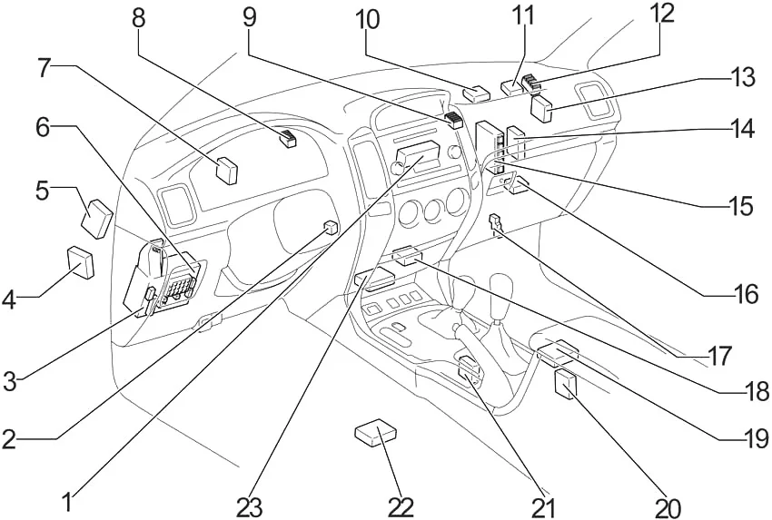
- Air conditioning control unit (automatic air conditioning (without navigation system))
- Transponder key amplifier
- Fuse box
- Suspension Control ECU
- ECU Slip Control (with VSC A/T)
- ECU Body
- ECU theft deterrent
- J/B №1
- J/B №2
- Sticky heater amplifier
- Computer with transponder key
- J/B №3
- ECU slip control (with VSC M/T)
- Air conditioning ECU (automatic climate control (with navigation system))
Air conditioning boost (manual air conditioning) - Engine and ECT ECU (A/T)
Engine ECU (M/T) - Center Lock Diff.
ECU Rear Differential Control Lock - Relay Box
- ECU Port
- ECU Navigation
- Coldbox Amplifier
- Gear Shift Interlock Control ECU
- Stereo Component Amplifier
- Airbag sensor assembly
Steering wheel on the right
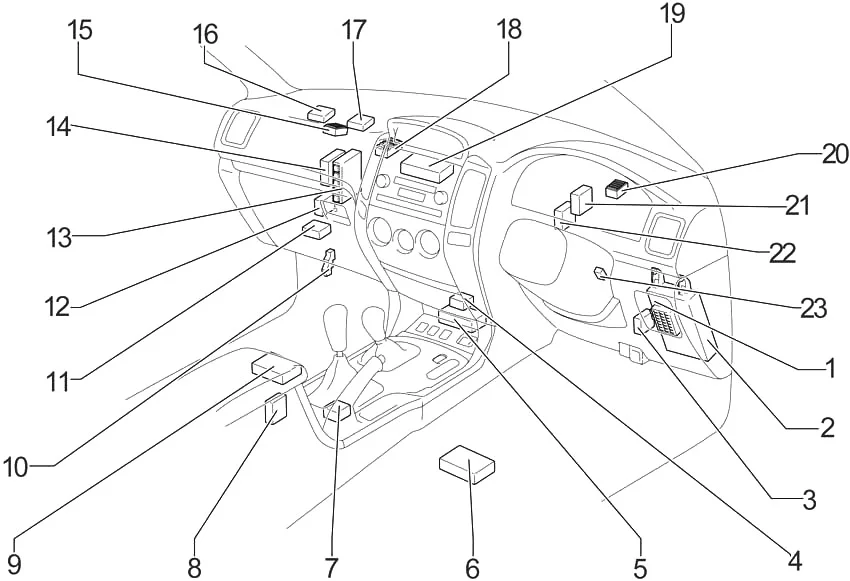
- ECU Body
- Fuse box
- ECU for slip control (with VOC)
- ECU port
- Airbag sensor unit
- ECU Navigation
- Gear Shift Interlock Control ECU
- Coldbox Amplifier
- Stereo Component Amplifier
- Relay Box
- Miscellaneous Locking Center
ECU rear differential control lock - ECU Suspension Control
- Engine and ECT ECU (A/T)
Engine ECU (M/T) - Air conditioning ECU (automatic climate control (with navigation system))
A/C booster (manual air conditioning) - J/B №3
- Computer with transponder key
- Sticky heater amplifier
- J/B №2
- Air conditioning control unit (automatic climate control (without navigation system))
- J/B №
- ECU theft deterrent
- Double Door Lock Control Relay
- Transponder Key Amplifier
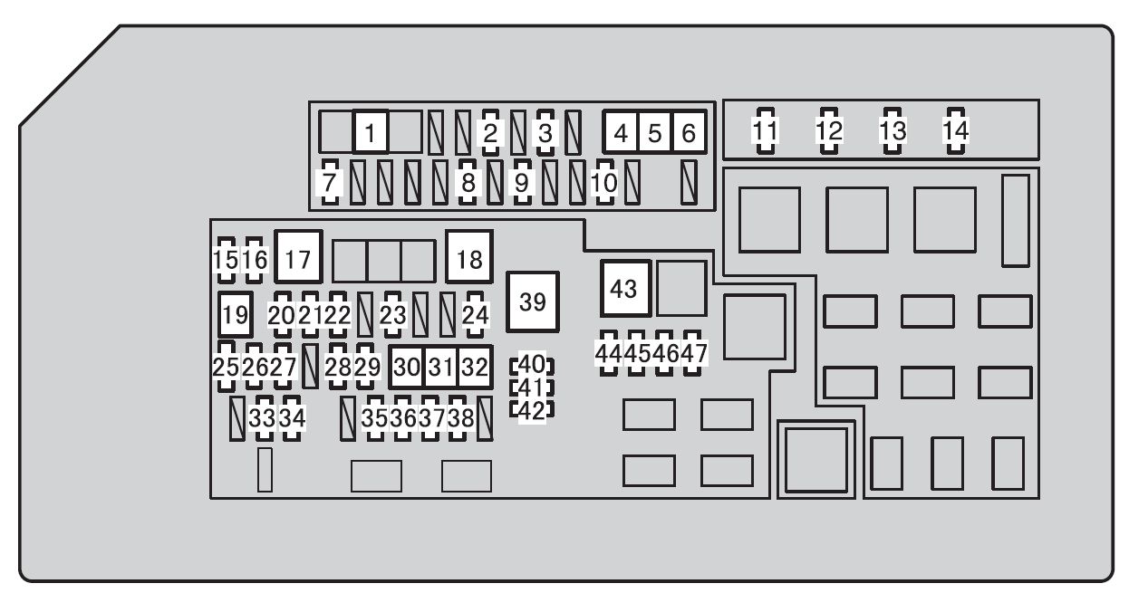
Diagram of the fuse box in the passenger compartment
The fuse panel is located behind the instrument panel cover on the driver’s side.
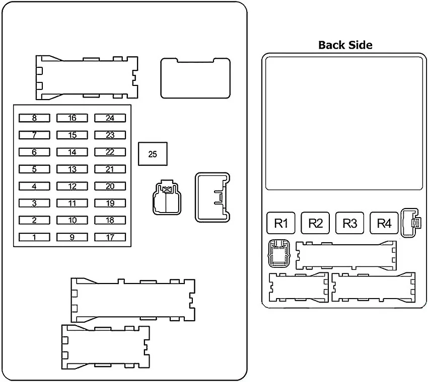
| Number | Amps [A] | Description |
| 1 | 10 | Electronically controlled fuel pump, multipoint fuel injection system/sequential multipoint fuel injection system, anti-lock braking system, active traction control system, vehicle stability control system |
| 2 | 10 | SRS airbags |
| 3 | 7,5 | Indicators and measurements |
| 4 | 7,5 | Multi-port fuel injection system/ sequential multi-point fuel injection system |
| 5 | 30 | Windshield wipers and washers |
| 6 | 20 | Electronic modulated suspension Toyotas |
| 7 | 20 | Rear differential lock system, center differential lock system |
| 8 | 15 | Rear window wiper |
| 9 | – | – |
| 10 | 30 | LHD: Power of the driver’s seat |
| 30 | RHD: Front passenger seat power | |
| 11 | 30 | LHD: front passenger seat power |
| 30 | RHD: Driver’s seat power | |
| 12 | 15 | Power Outlets |
| 13 | 10 | Air conditioning, refrigeration |
| 14 | 15 | Rear window washer |
| 15 | 10 | Shift lock control system, power windows, anti-lock braking system, active traction control system, vehicle stability control system, climate control system, power sunroof, power outlets |
| 16 | 10 | Anti-lock braking system, active traction control system, vehicle stability control system, climate control system, charging system, rear window defroster, reversing lights, turn signals, hazard warning lights |
| 17 | 7,5 | Electronically controlled fuel pump |
| 18 | 20 | Front passenger electric window |
| 19 | 20 | LHD: electric rear passenger window |
| 20 | RHD: Electric Rear Passenger Window | |
| 20 | 20 | LHD: electric rear passenger window |
| 20 | RHD: Electric Rear Passenger Window | |
| 21 | 10 | Dashboard Illumination |
| 22 | 10 | Tail lights, license plate lights, parking lights |
| 23 | 7,5 | Electronically controlled automatic transmission, power outlets, exterior mirrors, audio system |
| 24 | 10 | Lighter |
| 25 | 30 | Electric windows, electric moonroof |
| Relay | ||
| R1 | Horn | |
| R2 | Rear lights | |
| R3 | Power Relay | |
| R4 | Accessory socket (ACC SKT) | |
Relay box
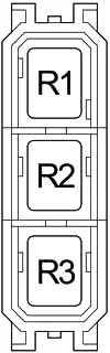
| Number | Relay |
| R1 | Relay panel |
| R2 | Reversing lights (BK/UP LP) |
| R3 | Outside rear-view mirror heaters (MIR HTR) |
Engine Compartment
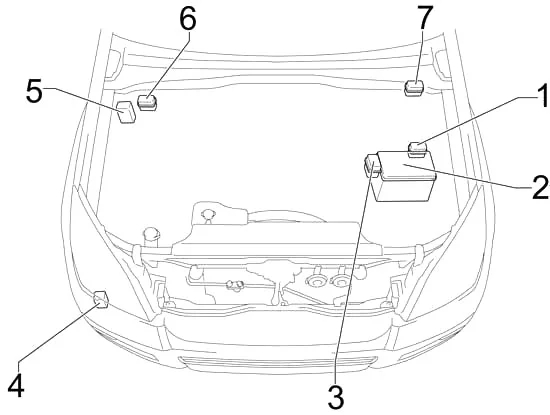
- Relay box №1
- Fuse box
- Relay box №2
- Headlight cleaning relay
- ECU slip control with actuator (no VSC)
- Relay box №3 (LHD)
- Relay Box 3 (RHD)
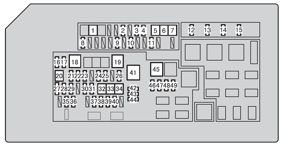
Diagram of the fuse box in the engine compartment

| Number | Amps [A] | Description |
| 1 | 10 | Backup fuse |
| 2 | 15 | Backup fuse |
| 3 | 20 | Electric cooling fan |
| 4 | 30 | Rear cooling system |
| 5 | 10 | Outside rear view mirror heaters |
| 6 | 10 | Stop lights, height-mounted stop light, gear lock control system, anti-lock braking system, active traction control system, vehicle stability control system, rear air suspension with height control |
| 7 | – | – |
| 8 | 15 | Front fog lamps |
| 9 | 7,5 | Viscous heater |
| 10 | 7,5 | On-board diagnostic system |
| 11 | 10 | Right Headlight (Low beam) |
| 12 | 10 | Left Headlight (Low beam) |
| 13 | 10 | Right Headlight (High beam) |
| 14 | 10 | Left Headlight (High beam) |
| 15 | 10 | O2 sensor and air flow meter |
| 16 | 7,5 | Air conditioning system |
| 17 | 30 | Rear window defogger |
| 18 | 10 | Height-adjustable rear air suspension system |
| 19 | 20 | Fuel Heater |
| 20 | 20 | Seat heating |
| 21 | 10 | Interior lighting, personal lighting, wireless remote control system, ignition switch light, door ceiling light |
| 22 | 20 | Public Address System |
| 23 | 10 | Anti-lock braking system, active traction control system, vehicle stability control system, air conditioning system, refrigerator, power windows |
| 24 | 10 | Multiplex communication system |
| 25 | – | Short pin |
| 26 | 7,5 | Charging system |
| 27 | – | – |
| 28 | 10 | Horn |
| 29 | 15 | A/F Sensor |
| 15 | 1KD-FTV: Fuel Pump | |
| 30 | 15 | Direction indicators, emergency flashers |
| 31 | 10 | Multi-port fuel injection system/ sequential multi-point fuel injection system |
| 32 | 20 | Electronically controlled fuel pump, fuel pump, multipoint fuel injection system/sequential multipoint fuel injection system |
| 25 | 1KD-FTV: Electronically controlled fuel pump, fuel pump, multipoint fuel injection system/sequential multipoint fuel injection system | |
| 33 | 20 | Electrical conductor window |
| 34 | 25 | Electric door closing system |
| 35 | – | – |
| 36 | 30 | Public Address System |
| 37 | 120 | without PTC: demist relay, ignition relay, “HEATER”, “CDS FAN”, “AM1”, “J/B”, “VISCUS”, “OBD”, “MIR HEATER”, “STOP”, “FR FOG”, “AIRSUS”, “RR A/C” and “STOP” fuses |
| 140 | with PTC: demist relay, ignition relay, “HEATER”, “CDS FAN”, “AM1”, “J/B”, “VISCUS”, “OBD”, “MIR HEATER”, “STOP”, “FR FOG”, Fuses “PTC-1”, “PTC-2”, “PTC-3”, “AIRSUS”, “RR A/C” and “STOP”. | |
| 38 | 50 | Air Conditioning System |
| 39 | 50 | Height-adjustable rear air suspension |
| 40 | 50 | All components in “ACC”, “CIG”, “IG1”, “IG1 №2”, “ECU-IG”, “FR WIP-WSH”, “RR WIP”, “RR WSH”, “DIFF”, “TEMS fuses” and “STA”. |
| 41 | 40 | Viscous heater |
| 42 | 50 | All items under “PWR OUTLET”, “P FR P/W”, “P RR P/W”, “D RR P/W”, “DP/ SEAT “, “PP/ SEAT “, “POWER”, “TAIL fuses” and “PANEL”. |
| 43 | 40 | Viscous heater |
| 44 | 40 | Viscous heater |
| 45 | 40 | Anti-lock braking system, active traction control system, vehicle stability control system |
| 46 | 30 | Starting system, “IGN”, “INDICATOR” and “SRS” fuses |
| 47 | 30 | no vehicle stability control system: anti-lock braking system, |
| 50 | with vehicle stability control system: Anti-lock braking system, active traction control system, vehicle stability control system | |
| 48 | 80 | Engine glow system |
| Relay | ||
| R1 | Electric cooling fan (CDS FAN) | |
| R2 | Accessories (ACC CUT) | |
| R3 | Fog lamps | |
| R4 | Starter (STA) | |
| R5 | Ignition (GI) | |
| R6 | Heater | |
| R7 | A/C compressor clutch (MG CLT) | |
| R8 | – | |
| R9 | Rear window defogger (DEFOG) | |
| R10 | Anti-lock braking system (ABS MTR) | |
| R11 | TRC MTR | |
| R12 | Anti-lock braking system (ABS SOL) | |
| R13 | Descent Assist Control System (DAC) | |
| R14 | Circuit opening relay (C/OPN)
or EDU |
|
| R15 | – | |
| R16 | EFI | |
| R17 | Air/Fuel Ratio Sensor (A/F HEAT) | |
| R18 | Fuel Pump | |
| R19 | Headlight (HEADLAMP) | |
Relay box №1

| Number | Courier |
| R1 | Starter (STA) |
| R2 | GLOW System |
Relay box №2
| Number | Courier |
| R1 | Air Suspension (AIR SUS) |
| R2 | Dimmer (with continuous daylight) |
Relay box №3

| Number | Courier |
| R1 | PTC №1 |
| R2 | PTC №2 |
| R3 | PTC №3 |