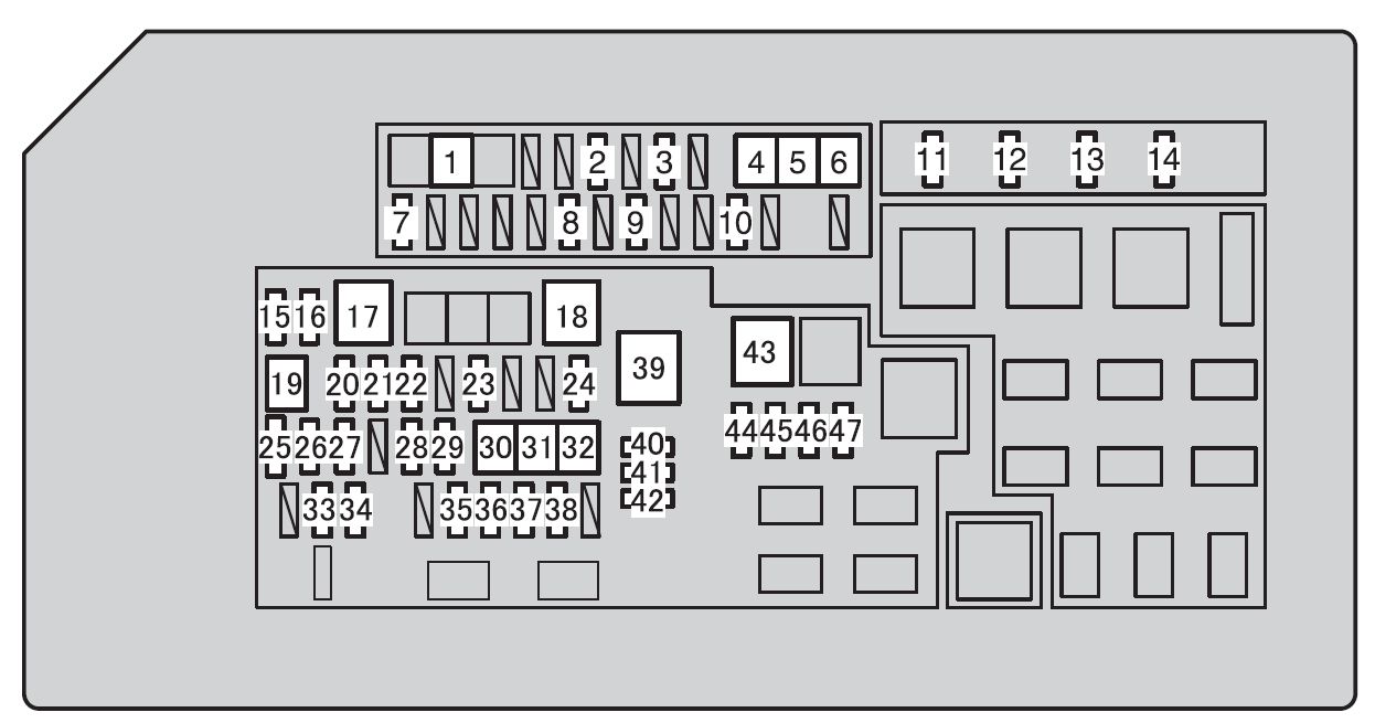
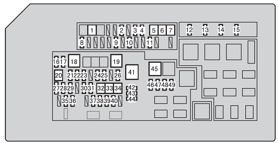
Fuse and relay box diagrams – Toyota Land Cruiser 80/J80
Applies to vehicles manufactured over the years:
1990, 1991, 1992, 1993, 1994, 1995, 1996, 1997.
Fuse 1 in the instrument panel fuse box accounts for the cigarette lighter (power outlets).
Passenger compartment fuse box
Location
Description
- Fuse Box
- ABS ECU
- Open Circuit Relay
- Relay box
- Central differential lock control relay
- Seat belt warning relay
- Light Control Relay
- Cruise control ECU
- A/C system booster
- Engine coolant temperature, cut-off relay
- Blower speed control relay
- A/C Booster
- Engine Control Module
- Stereo component amplifier
- ECU Differential Lock
- Light Cylinder Ignition Switch Relay
- Airbag sensor assembly
Located behind the cover on the driver’s side instrument panel.
| Number | Amps [A] | Description |
| 1 | 15A | Lighter;
Electric rear-view mirrors; Digital clock display; Radio; Cassette recorder; Power antenna; Automatic shift locking; SRS airbag system. |
| 2 | 15A | Tail lights;
License plate illumination; Parking lights and front markers; Instrument panel illumination; Clock; Glove box illumination. |
| 3 | 15A | On-Board Diagnostic System |
| 4 | 10 A | Traffic lights;
Multipoint fuel injection system/sequential multipoint fuel injection system; Cruise control override device; Automatic shift lock. |
| 5 | 20A | Rear window defogger |
| 6 | 20A | Windshield wiper and washer;
Rear window wiper and washer. |
| 7 | 10 A | Counter and indicators;
Service warning indicators and warning bells (except flush and open door warning lights); Emergency lights. |
| 8 | 7,5A | Switching on the signal lights |
| 9 | 15A | Cruise Control System |
| 10 | 10 A | SRS airbag system |
| 11 | 20A | Air Conditioning System |
| 12 | 7,5A | Multipoint fuel injection system/sequential multipoint fuel injection system;
Emission control system; SRS airbag system. |
| 13 | 10 A | Air conditioning system |
| 14 | 30A | Differential locking system |
| 15 | – | Not used |
| 16 | – | Not used |
| 17 | – | Not used |
| 18 | 40A | Air Conditioning System |
| 19 | 30A | Electric windows;
Electric door closing system; Electric sunroof. |
Relay box
| Number | Courier |
| R1 | Fogger |
| R2 | Heater |
| R3 | Power Relay |
| R4 | Tail lights |
| R5 | Blinker |
| R6 | Not used |
| R7 | Cooling Fan |
| R8 | Blower – high speed |
Additional components
Description
- Opening roof control relay
- Rear Heater Relay
- Subwoofer amplifier
- Rear wiper relay
- ECU Shift Interlock
- Door lock control relay.
Fuse box in engine compartment
Location
Description
- Junction box
- Fuse and relay box
- Insert high power fuse connection
The fuse box is located near the battery.
| Number | Amps [A] | Description |
| 1 | – | Not used |
| 2 | 7,5A | Charging system;
Flush warning light. |
| 3 | 15A | Multi-port fuel injection system/ sequential multi-point fuel injection system |
| 4 | 20A | No circuit |
| 5 | 15A | Headlights upright |
| 6 | 15A | Left Headlights |
| 7 | – | Not used |
| 8 | – | Not used |
| 9 | 15A | Emergency lights, horns |
| 10 | 10 A | Interior lighting;
Personal Enlightenment; Startup lighting; Ignition switch light; Open door warning light; Clock; Radio; Cassette recorder; Power antenna; Hygienic lights. |
| 11 | 50A | All components in the “CIG”, “WIPER”, “GAUGE”, “TURN”, “ECU-IG”, “REAR-HTR”, “IGN”, “DIFF” and “FL POWER” circuits. |
| 12 | 60A | Wheel-lock prevention system |
| Relay | ||
| R1 | Main EIF | |
| R2 | Horn | |
| R3 | Not used | |
| R4 | Not used | |
| R5 | Headlight | |
| R6 | Not used |


