Toyota Land Cruiser 100 (1998-2007) – fuse box diagram
Year of manufacture: 2000, 2001, 2002, 2003, 2004, 2005, 2006, 2007.
Lighter fuse (power outlet) on Land Cruiser 100 (1998-2007). Is fuse 2 in the fuse box in the passenger compartment.
Passenger compartment
LHD
1998-2003

2003-2007

RHD

- ’98 -’03: Blinker indicator
- ’98 -’03: Fuse box
’03 -’07: Fuse box / ECU module - ’98 -’03: ABS ECU
- Tilt and telescope controller
- Computer with transponder key
- ’98 -’03: wireless door lock ECU
- ’98 -’03: ECT ECU
- ’98 -’03: ECU Suspension Control
- Transponder Key Amplifier
- ’98 -’03: ECU Instrument
- Anti-theft ECU
- Automatic antenna relay
- Engine and ECT ECU
- Central differential lock control relay
- ’98 -’03:
ECU front/rear lock control
or
ECU rear lock control - ’98 -’03: Cruise control calculator
- ’98 -’03: Connection block ( MTR relay )
’03 -’07: Fuse box - ’98 -’03: Viscose heating amplifier
- ’98 -’03: ECU Center
- ’98 -’03: ABS Deceleration Sensor
- Central airbag sensor mounting
- ’98 -’03: AHC main relay
- ’98 -’03:
RHD:Preheat Timer
- 03-07: Air conditioning control (with navigation system)
- 03-07: Connection block
- 03-07: Bonding block
- 03-07: Bonding block
- 03-07: Bonding block
- 03-07: ECU Port
- ’03 -’07: Shift lock control ECU
- ’03 -’07: Air conditioning control (without navigation system)
- ’03-07: ABS and BA and TRAC and VSC ECU
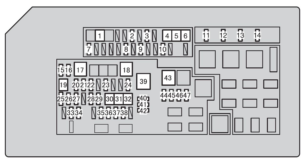
Passenger compartment fuse box (19 98-2003 )

| No. |
Fuse |
Amp [A] |
Description |
| 1 | MIRR | 10 | Electric Rear View Mirror |
| 2 | SRS | 15 | SRS airbag system;
Seat belt pretensioners. |
| 3 | CIGAR | 15 | Lighter;
Car audio system; Power antenna, |
| 4 | IGN | 10 | Multi-port fuel injection system;
Multi-port sequential fuel injection system; Anti-lock braking system; SRS airbag system; Seat belt pretensioners; Flush warning light. |
| 5 | POWER | 40 | Control system for electric door locks;
Electrically operated windows; Electric Opening Roof; Electrically adjustable seat; Electric reclining and telescoping steering. |
| 6 | DOME | 10 | Interior lighting;
Personal Illumination. |
| 7 | AHC-IG | 20 | Active suspension with height control (AHC) |
| 8 | DIFF | 20 | Rear differential lock |
| 9 | GAUGE | 15 | Indicators and metrics;
Service indicators and Warning bell (except for unloading, opening doors and SRS airbag warning lights); Reversing lights; Air conditioning system; Electronically controlled automatic transmission; Wireless remote control system; Continuous daylighting system. |
| 10 | WIPER | 20 | 1998-2000:
Windshield wipers and washers; Rear window wiper and washer. |
| 25 | 2001-2002:
Windshield wipers and washers; Rear window wiper and washer. |
||
| 11 | I / UP | 7.5 | Engine Idle System |
| 12 | FR FOG | 15 | Front fog lamps |
| 13 | STOP | 15 | Traffic lights;
Height-mounted stop light. |
| 14 | RR AC | 30 | Air conditioning system |
| 15 | DEFOG | 20 | Rear window defogger |
| 16 | ECU-B | 15 | Assisted tilt and telescopic steering;
Daytime running light system; Theft deterrent system. |
| 17 | TAIL | 15 | Tail lights;
License plate illumination; Parking lights; Instrument panel illumination. |
| 18 | AHC-B | 15 | Active suspension with height control (AHC) |
| 19 | OBD | 10 | On-Board Diagnostic System |
| 20 | RR HTR | 10 | Air conditioning system |
| 21 | ECU-IG | 15 | Anti-lock braking system;
Shift lock system; Power seats; Antenna; Deflection system and telescopic steering system. |
| 22 | PWR OUTLET | 15 | Power Outlets |
| No. |
Relay |
| R1 | Open circuit (fuel pump (C / OPN)) |
| R2 | Fuel pump (FUEL / PMP) |
| R3 | (D / L (L)) |
| R4 | (SPIL / VLV) |
| R5 | Starter (ST / CUT) |
| R6 | (D / L (U)) |
| R7 | Front fog light (FR FOG) |
| R8 | – |
| R9 | Rear window defogger (DEFOG) |
| R10 | Electrically operated windows;
Electric sunroof(POWER). |
| R11 | Rear heater (RR HTR) |
| R12 | Interior lights (DOME) |
| R13 | Tail lights (TAIL) |
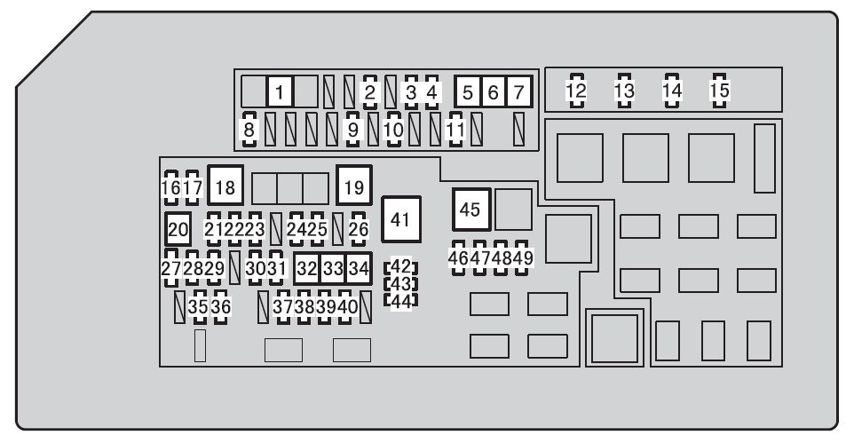
Passenger compartment fuse box (left (2003-2007))

| No. |
Fuse |
Amp [A] | Description |
| 1 | PWR OUTLET | 15 | Power Outlets |
| 2 | IGC | 15 | Lighter |
| 3 | ACC | 7.5 | Dashboard Illumination |
| 4 | AM1 | 7.5 | Multi-port fuel injection system;
Multi-port sequential fuel injection system. |
| 5 | DEFOG | 20 | Rear window defogger |
| 6 | AHC – B | 15 | Active suspension with height control (AHC) |
| 7 | HTR FUEL | 20 | Fuel Heater |
| 8 | HTR POWER | 7.5 | Electric heater |
| 9 | AHC-IG | 20 | Active suspension with height control (AHC) |
| 10 | EFI NO.2 | 10 | Emission control system |
| ECD NO.2 | 10 | Emission control system | |
| 11 | GAUGE1 | 10 | Meters and gauges |
| 12 | ECU-IG1 | 10 | Multi-port fuel injection system;
Multi-port sequential fuel injection system. |
| 13 | ECU-B1 | 10 | Navigation System |
| 14 | DBL LOCK | 15 | Double-locking system |
| 15 | POTATO LOAD | 30 | Trailer loading system |
| 16 | A / C | 15 | Air Conditioning System |
| 17 | STOP | 15 | Stoplights |
| 18 | OBD – 2 | 7.5 | On-board diagnostic system |
| 19 | IDEL UP | 7.5 | Idle System |
| 20 | LH SEAT | 30 | Electric seating system |
| 21 | DOOR | 25 | Electric locking system;
Electric windows. |
| 22 | SUN ROOF | 25 | Electronic sunroof |
| 23 | RR WIPER | 15 | Rear Windshield Wiper |

| No. |
Courier |
| R1 | Rear window defogger (DEFOG) |
| R2 | Ignition (IG1 No 2) |
| R3 | Ignition (ACC) |
| R4 | Interior lights (DOME) |
Passenger compartment fuse box (right (2003-2007))

| No. |
Fuse |
Amp [A] |
Description |
| 1 | ECU – B2 | 10 | Door locking system;
Electric window. |
| 2 | DIFF | 20 | Four Wheel Drive |
| 3 | WASHER | 15 | Windshield washer |
| 4 | RADIO | 10 | Sound system |
| 5 | DOME | 10 | Interior lights |
| 6 | VGRS | 40 | Variable ratio steering system |
| 7 | P / W (FL) | 20 | Supply of windows |
| 8 | P / W (RL) | 20 | Supply of windows |
| 9 | WIPER | 25 | Windshield Wiper |
| 10 | ECU-IG2 | 10 | Rear air conditioning system |
| 11 | SEAT HTR | 15 | Seat warmer |
| 12 | GAUGE2 | 10 | Backup Lights |
| 13 | MET | 7.5 | Counters and Meters |
| 14 | ING | 7.5 | Multi-port fuel injection system;
Multi-port sequential fuel injection system. |
| 15 | SECURITY | 7.5 | Theft deterrent system |
| 16 | P / W (RR) | 20 | Supply of windows |
| 17 | P / W (FR) | 20 | Supply of windows |
| 18 | POTATO LOAD | 30 | Trailer Loading System |
| 19 | – | – | – |
| 20 | TIL AND TEL | 20 | Pivoting and telescopic steering |
| 21 | RR A / C | 30 | Rear air conditioning system |
| 22 | RH BANKS | 30 | Electric seating system |

| No. |
Courier |
| R1 | Stop lights (STOP LP) |
| R2 | – |
| R3 | Ignition (IG1 No 3) |
| R4 | Accessories (ACC CUT) |
Liftgate

Swing

- Sunroof control unit
- RHD: ECU Remote Mirror Control
- Stereo Component Amplifier
- A/C Amplifier
- Rear radiator relay
- Liftgate type: Rear wiper relay
- Trailer Hitch Relay
- Trailer Convertor Relay
- ECU Fuel Pump Control
- Fuel pump selection relay
- Replacement relay for auxiliary fuel pump
- ’03 -’07: TV camera ECU
- ’03-07: Navigation ECU
- Rear heater relay
- Control valve assembly
- LHD: ECU Remote Mirror Control
- Swing type: RH Rear Wiper Relay
- Swing type: Rear wiper relay LH
Engine compartment

- Injection Controller (EDU)
- Main winch relay
- Glow Plug Relay
- Fuse Box
- Fuse Blocks
- LH Headlight Control
- Sticky Heater Relay
- Water Temperature Cutout Relay
- A/C Condenser Fan Relay
- Headlight Washer Control Relay
- Headlight Washer Control ECU RH
- Fuse connection block (cold area)
- Daylight relay continuous 3
- Intake Heater Relay
Engine Compartment Fuse Box (1998-2003)

| No. |
Fuse |
Amp [A] | Description |
| 1 | AM1 No. 2 | 20 | Startup system;
Direction indicators; Emergency lights; All fuse items “CIGAR”, “ECU-IG”, “MIRR”, “SRS”. |
| 2 | AC | 20 | Air conditioning system |
| 3 | HTR POWER | 10 | PTC Heater |
| 4 | SEAT HTR | 15 | Seat warmers |
| 5 | HTR FUEL | 20 | Fuel Heater |
| 6 | MIR HTR | 15 | Exterior view mirror heater |
| 7 | CLNER HQ | 20 | Headlight cleaning |
| 8 | CDS FAN | 20 | Electric cooling fan |
| 9 | EFI | 20 | Multi-port fuel injection system;
Multi-port sequential fuel injection system; Emission control system; Fuel pump. |
| ECD | 20 | Multi-port fuel injection system;
Multi-port sequential fuel injection system. |
|
| 10 | HORN | 10 | Horn |
| 11 | THROTTLE | 15 | Electronic Throttle Control System |
| 12 | RADIO | 20 | Car Audio System |
| 13 | HAZ-TRN | 15 | Emergency Lights;
Turn signals. |
| 14 | AM2 | 30 | Starting system;
Multi-port fuel injection system; Multi-port sequential fuel injection system; All “IGN” fuse components. |
| 15 | ECU-B1 | 20 | Control system for electric door locks;
Electrically operated windows, w Rear window wiper and washer; Illuminated entry system; Wireless remote control system; Electric rear view mirror; Gauges and meters; Air conditioning system; Automatic lighting control system; Burglary deterrent system. |
| 16 | HEAD (LH-UPR) | 20 | Left Headlight (High beam) |
| 17 | HEAD (RH-UPR) | 20 | Headlight (High beam) |
| 18 | HEAD (LH-LWR) | 10 | Left headlight (dipped beam);
Front fog lights. |
| 19 | HEAD (RH-LWR) | 10 | Right Headlight (Low beam) |
| 20 | ABS NO.1 | 40 | 1998-1999:
Anti-lock Braking System |
| 50 | 2000-2003:
Anti-lock Braking System |
||
| 21 | AHC | 50 | Active suspension with height control (AHC) |
| 22 | ACC | 50 | Fuse “PRW OUTLET”. |
| 23 | AM1 NO.1 | 80 | Charging system;
All components in “AM1 NO.2”, “GAUGE”, “WIPER”, “. |
| 24 | HTR | 60 | Air Conditioning System |
| 25 | GLOW | 80 | Engine Gloss System |
| 26 | ABS NO.2 | 40 | Anti-lock Braking System |
| 27 | STARTER | 30 | Starting System |
| Relay |
|||
| R1 | A/C Compressor Clutch (MG CLT) | ||
| R2 | Defogger exterior rear-view mirror (MIR HTR) | ||
| R3 | Accessories (ACC) | ||
| R4 | Active suspension with height control (AHC) | ||
| R5 | Ignition (IG1 No. 1) | ||
| R6 | Ignition (IG1 No. 2) | ||
| R7 | Anti-lock braking system (ABS SOL) | ||
| R8 | Engine control unit (EFI);
Engine Control Unit (ECD). |
||
| R9 | Horn | ||
| R10 | Resistor | ||
| R11 | Starter | ||
| R12 | Anti-lock braking system (ABS MTR2) | ||
| R13 | Headlight (HEADER) | ||
| R14 | Anti-lock braking system (ABS MTR1) | ||
Engine compartment fuse box (2003-2007)

| No. |
Fuse |
Amp [A] |
Description |
| 1 | – | – | – |
| 2 | – | – | – |
| 3 | – | – | – |
| 4 | – | – | – |
| 5 | ST1 | 7.5 | 2003-2005:
Mutiport fuel injection system; Sequential multi-port fuel injection. |
| WIP-S | 7.5 | 2006-2007: – | |
| 6 | TOLLING | 30 | Trailer Lights |
| 7 | MIR HTR | 15 | External Defogger Rear View Mirror |
| 8 | RR HTR | 10 | Rear air conditioning system |
| 9 | HAZ-TRN | 15 | Emergency Lights;
Turn signals. |
| 10 | ALT – S | 7.5 | Charging system |
| 11 | NV-IR | 20 | |
| 12 | FR FOG | 15 | Fog Lights |
| 13 | BRK TOLLER | 30 | Trailer Lights |
| 14 | CLNER HQ | 20 | Headlight cleaning |
| 15 | FR – IG | 10 | Charging system |
| 16 | PLATE | 7.5 | Dashboard Illumination |
| 17 | TOURNAMENT TABLE | 30 | Trailer Lights |
| 18 | OGON | 15 | Parking lights, tail lights |
| 19 | NIETOPERZ | 30 | Fuse “ECU-B2” |
| 20 | TEL | 7.5 | |
| 21 | AMP | 30 | Public Address System |
| 22 | FEI NO. 1 | 25 | Multi-port fuel injection system;
Sequential multi-port fuel injection. |
| ECD NO. 1 | 25 | Multi-port fuel injection system;
Sequential multi-port fuel injection. |
|
| 23 | AM2 | 15 | Fuse “IGN |
| 24 | ETCS | 10 | Multi-port fuel injection system;
Sequential multi-port fuel injection. |
| 25 | HORN | 10 | Horn |
| 26 | – | – | – |
| 27 | HEAD (RH-LWR) | 10 | Right Headlight (Low beam) |
| 28 | HEAD (LH-LWR) | 10 | Left Headlight (Low beam) |
| 29 | HEAD (RH-UPR) | 20 | Headlight (High beam) |
| 30 | HEAD (LH-UPR) | 20 | Left Headlight (High beam) |
| 31 | ABS NO. 2 | 40 | Anti-lock Braking System |
| 32 | ABS NO. 1 | 50 | Anti-lock Braking System |
| 33 | AHC | 50 | Active suspension with height control (AHC) |
| 34 | DISTRIBUTOR | 30 | Starting system |
| 35 | PIN TO SHORT | – | Fuses “BAT”, “AMP |
| 36 | PIN B SHORT | – | Fuses “HAZ-TRN”, “ALT-S |
| 37 | POŚWIATA | 80 | Engine Gloss System |
| Relay |
|||
| R1 | Heater (HTR) | ||
| R2 | Anti-lock braking system (ABS MTR1) | ||
| R3 | Anti-lock braking system (ABS MTR2) | ||
| R4 | Anti-lock braking system (ABS SOL) | ||
| R5 | Engine Control Unit (EFI) Engine control unit (ECD) |
||
| R6 | Active suspension with height control | ||
| R7 | Open Circuit (Fuel Pump (C / OPN)) | ||
| R8 | Fuel Pump (F / PUMP) | ||
| R9 | Starter | ||

| No. |
Courier |
| R1 | Cooling System |
| R2 | A/C compressor clutch (MG CLT) |
| R3 | Electric cooling fan (CDS FAN) |
| R4 | Horn |
| R5 | Headlight (HEADER) |
| R6 | Driving Lights (HEAD HI) |
| R7 | Defogger outside rear-view mirror (MIR HTR) |
| R8 | Rear Heater (RR HTR) |
| R9 | Instrument panel (PANEL) |
| R10 | Front Fog Light (FR FOG) |
| R11 | Ignition (GI No. 1) |
| R12 | Tail lights (TAIL) |
Fuse Connection Block (1998-2003)

| No. |
Fuse |
Amp [A] |
Description |
| 1 | J / B NO 2 | 100 | All components in “ECU-B”, “FR FOG”, “DEFOG”,
“AHC-B”, “TAIL”, “STOP”, “DOME”, “POWER”, “OBD”, “RR AC” and “RR HTR”. |
| 2 | ALT | 140 | All elements in fuses
“J / B NO.2”, “MIR HTR”, “AM1 NO.1”, “ACC”, “CDS FAN”, “HTR” and “ABS NO.1”. |
| 3 | MAIN | 100 | “ECU-B”, “FR FOG”, “DEFOG” fuses,
“AHC-B”, “OBD”, “TAIL”, “STOP”, “DOME-TOWER”, “RR AC”, “RR HTR”. |
| 4 | ALT-S | 7.5 | Charging system |
Fuse Connection Block (2003-2007)
| No. |
Fuse |
Amp [A] |
Description |
| 1 | HTR | 50 | Air Conditioning System |
| 2 | J / B NO 1 | 120 | Relay “IG1 NO.1”, “TAIL”, “MIR HTR”,
“RR HTR”, “TOW BRK”, “TOW”; FOG “FR FOG” fuses. |
| 3 | J / B NO 2 | 120 | “IG1 No. 2”, “ACC”, “DEFOG” relay,
“AM1”, “LH SEAT”, “STOP”, “ECU-B1”, “SUNROOF”, “OBD-2”, “DOOR”. |
| 4 | J / B NO 3 | 120 | Relay “IG1 NO.3”, “SECURITY”, “TIL & TEL; TEL”,
“RH SEAT”, “RR A / C”, “P / W (RR)”, “P / W (RL)”, “P / W (FR) “,” P / W (FL) “. |
| 5 | MAIN | 100 | “HEAD HI”, “HEAD”, “ABS NO 1” relay,
“ABS NO 2”, “SHORT PIN A”, “EFI OR ECD NO 1”, “SHORT PIN B”, “AM2”; “STARTER”, “HORN”, “ECTS” fuses. |
| 6 | ALT | 140 | Fuses “J / B NO.1”, “J / B NO.2”,
“J / B NO.3”, “HTR”. |