Fuse diagrams and relay boxes – Suzuki(Maruti) Ritz
Applies to vehicles manufactured over the years:
2009, 2010, 2011, 2012, 2013, 2014, 2015, 2016.
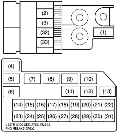
Instrument panel fuse box diagram
The fuse box is located under the instrument panel on the driver’s side. Push on both ends and lift the cover to remove it. To remove the fuse, use the fuse puller located in the fuse box.
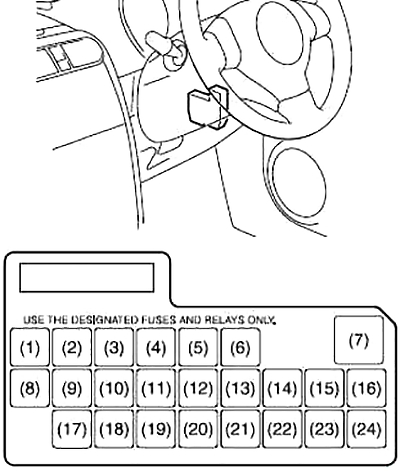
| Number | Amps [A] | Description |
|---|---|---|
| 1 | – | – |
| 2 | 15 | Ignition Coil |
| 3 | 10 | Backup Light |
| 4 | 10 | Counter |
| 5 | 15 | Accessories 1 |
| 6 | 15 | Accessories 2 |
| 7 | 30 | Supply of windows |
| 8 | 15 | Window Washer |
| 9 | 10 | IG1 SIG |
| 10 | 15 | Airbag |
| 11 | 10 | Wheel-lock prevention system |
| 12 | 10 | Rear light |
| 13 | – | – |
| 14 | 20 | Door Lock |
| 15 | – | – |
| 16 | 10 | SIG ST |
| 17 | 10 | Immobilizer |
| 18 | 10 | IG2 SIG |
| 19 | 15 | Rear fog light |
| 20 | 15 | Radio |
| 21 | 20 | Rear fog |
| 22 | 15 | Horn and hazard lights |
| 23 | – | – |
| 24 | – | – |
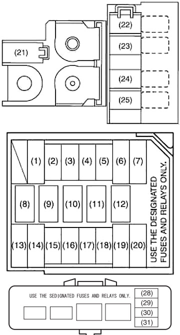
Fuse box in engine compartment
The main fuse, primary fuses, and some individual fuses are located in the engine compartment. If the main fuse blows, no electrical components will operate. If the main fuse blows, no electrical components in the corresponding load group will operate.
Diagram (gasoline)
| Number | Amps [A] | Description |
|---|---|---|
| 1 | 80 | All electric charge |
| 2 | 50 | Window supply, ignition.
Windshield wiper, starter |
| 3 | 50 | Tail light, rear defroster, door lock, hazard lights/horns, dome |
| 14 | 30 | Heater fuse |
| 15 | 15 | Fuel injection |
| 16 | 10 | Air Compressor |
| 17 | 15 | A/T controller supply |
| 18 | 15 | Brake Light Switch |
| 19 | 30 | ABS control module |
| 20 | 30 | Starter motor |
| 21 | – | – |
| 22 | 50 | Power steering control module |
| 23 | 30 | Ignition Switch |
| 24 | 30 | Radiator Fan |
| 25 | – | – |
| 26 | 30 | ABS control module |
| 27 | – | – |
| 28 | – | – |
| 29 | 15 | Front fog light |
| 30 | 15 | Headlight (left) |
| 31 | 15 | Lighthouse (right) |
| 32 | 80 | Heater, air compressor, power steering |
| 33 | 80 | Radiator Fan, Front Fog Light, Headlight |
| 4 | Radiator Fan Relay #1 | |
| 5 | Radiator Fan Relay No. 2 | |
| 6 | Radiator Fan Relay #3 | |
| 7 | Starter Relay | |
| 8 | Main Relay | |
| 9 | – | |
| 10 | Front fog light relay | |
| 11 | Fuel Pump Relay | |
| 12 | Air Compressor Relay | |
| 13 | A/T Relay | |
Diagram (Diesel)
| Number | Amps [A] | Description |
|---|---|---|
| 1 | 30 | Starting the engine |
| 2 | 10 | Air Compressor |
| 3 | 15 | Fuel Pump |
| 4 | 30 | FI |
| 5 | 30 | Heater |
| 6 | 30 | Radiator Fan |
| 7 | 50 | Power Steering Control Module |
| 13 | 30 | ABS control module |
| 14 | 30 | ABS control module |
| 15 | 15 | Brake Light Switch |
| 16 | 15 | Lighthouse (right) |
| 17 | 15 | Headlight (left) |
| 18 | 15 | Front fog light |
| 19 | 30 | Ignition switch |
| 20 | 50 | Window power supply. Ignition, wiper, starter |
| 21 | 100 | All electric charges |
| 22 | 100 | ABS, MIL, front fog |
| 23 | 100 | EPS, radiator fan. Heater, starter |
| 24 | 50 | Lamp |
| 25 | 100 | Glow |
| 26 | 30 | – |
| 27 | 30 | – |
| 28 | – | – |
| 29 | 20 | FI fuse |
| 30 | – | – |
| 31 | 10 | FI3 |
| 8 | Radiator Fan Relay #1 | |
| 9 | Radiator Fan Relay #2 | |
| 10 | Radiator Fan Relay #3 | |
| 11 | Air Compressor Relay | |
| 12 | Starter Relay | |