Fuse diagrams and relay boxes – Suzuki Kizashi
Applies to vehicles manufactured over the years:
2010, 2011, 2012, 2013, 2014.
Instrument panel fuse boxes
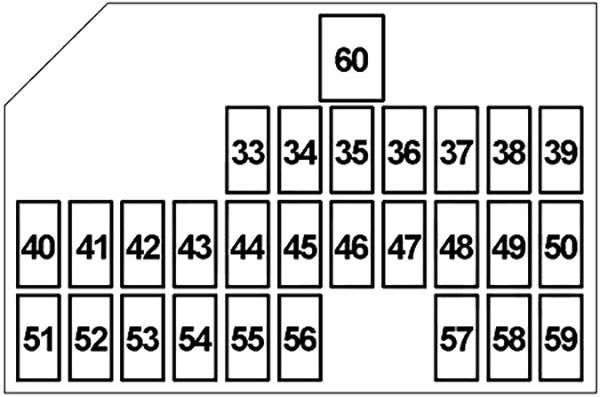
Driver’s side
The fuses are located under the instrument panel on the driver’s side. To access these fuses, pull the lower instrument panel cover to release the latches and then remove the lower cover. The amperage of each fuse is shown on the top of the lower instrument panel cover.
Fuse box diagram
| Number | Amps [A] | Description |
|---|---|---|
| 33 | 15 | Windshield washer motor, body control module (BCM) |
| 34 | 20 | Seat warmer |
| 35 | 25 | Wiper Motor, Wiper Relay, Hi/Lo Windshield Relay |
| 36 | 7,5 | Rain and light sensor, rear defroster relay, keyless start control module, roof module, auto-dimming rear view mirror, fan motor relay, headlight washer control module |
| 37 | 15 | Generator, ignition coil #1-#4, engine control module (ECM) |
| 38 | 15 | Accessory socket no. 2 |
| 39 | 15 | Accessory socket 1, mirror power switch, keyless start control module, seat control module, audio system, navigation |
| 40 | – | – |
| 41 | – | – |
| 42 | 10 | Electronic Stability Program Control Module (ESP), steering angle sensor |
| 43 | 7,5 | Brake light switch, cruise control |
| 44 | 7,5 | Continuously variable transmission (CVT), four-wheel drive (4WD) control module, P/S control module |
| 45 | 7,5 | – |
| 46 | 7,5 | Automatic climate control panel, body control module (BCM), keyless start control module, combination counter |
| 47 | 10 | Transmission range sensor, body control module (BCM), parking sensor system control module, ESP OFF/parking sensor switch, seat power control module, automatic headlight leveling control module, HVAC control module, seat heater, reverse light switch |
| 48 | 10 | Airbag module (SDM) |
| 49 | 15 | Keyless start control module, steering lock |
| 50 | 7,5 | Keyless start control module, body control module (BCM) |
| 51 | 20 | Roof Unit |
| 52 | 7,5 | Rear fog light relay |
| 53 | 10 | Back Light Relay |
| 54 | 10 | Brake Light Switch |
| 55 | 10 | Threat spark, body control module (BCM) |
| 56 | 20 | Windshield main switch, windshield motor (driver’s side), windshield auxiliary switch, windshield motor (passenger’s side) |
| 57 | 15 | Audio, Navigation |
| 58 | 10 | Engine Control Module (ECM), Body Control Module (BCM), Keyless Start Control Module, Engine Switch, Automatic Air Conditioning Panel, Data Link Connector (DLC), Combination Meter, Console, Rear Dome Light, Vanity Light, Ceiling Light, Trunk Light, Glovebox Light, Footwell Light, HVAC Control Module |
| 59 | 20 | Door lock, body control module (BCM), engine relay 1 and 2 fuel engine cover |
| 60 | 30 | Main window switch, rear window auxiliary switch |
| R1 | Ignition (IG2) | |
| R2 | Ignition (IG1) | |
| R3 | Accessory | |
| R4 | Back Light | |
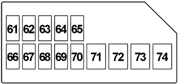
Passenger side
The fuses are also located under the instrument panel on the passenger side. Remove the two screws and remove the instrument panel cover.
Fuse box diagram
| Number | Amps [A] | Description |
|---|---|---|
| 61 | 20 | Rear window (right) |
| 62 | 20 | Rear window (left) |
| 63 | 20 | Windshield main switch, auxiliary windshield main switch, windshield motor |
| 64 | 15 | Four-wheel drive (4WD) control module |
| 65 | 20 | Battery Fan |
| 66 | – | – |
| 67 | – | – |
| 68 | – | – |
| 69 | – | – |
| 70 | – | – |
| 71 | 20 | Sound Amplifier |
| 72 | 30 | Right seat ( electric seat control module, lumbar support switch, auxiliary electric seat switch ) |
| 73 | 30 | Left seat (electric seat control module, lumbar support switch, auxiliary electric seat switch) |
| 74 | 30 | – |
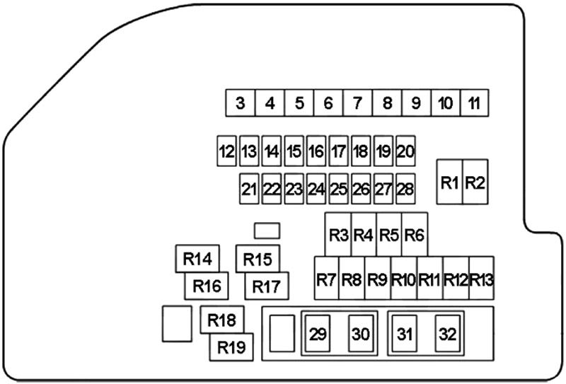
Diagram of the fuse box in the engine compartment
The main fuse, primary fuses, and some individual fuses are located in the engine compartment. To remove a fuse, use the fuse puller located in the fuse box. The current rating of each fuse is shown on the back of the fuse box cover.
| Number | Amps [A] | Description |
|---|---|---|
| 3 | 50 | Blower motor relay |
| 4 | 50 | Fuse box in passenger compartment 2 (electric window, electric seat ) |
| 5 | 50 | Fuse box in passenger compartment 1 (keyless start control module) |
| 6 | 40 | Electronic Stability Program Control Module (ESP) |
| 7 | 40 | Fuse box in passenger compartment 1 (lights) |
| 8 | 30 | Starter Relay |
| 9 | 30 | Radiator Fan Relay #1 |
| 10 | 30 | Radiator Fan Relay #3 |
| 11 | 50 | Fuse box in passenger compartment 1 (ignition switch) |
| 12 | 25 | Fuse box in passenger compartment 1 (spare) |
| 13 | 25 | Electronic Stability Program Control Module (ESP) |
| 14 | 20 | Main relay (motor control) |
| 15 | 7,5 | High beam relay, low beam relay (left and right) |
| 16 | 30 | Headlight Washer Motor |
| 17 | 30 | Rear defogger relay |
| 18 | 15 | Throttle actuator control relay |
| 19 | 15 | Mirror Heater Relay |
| 20 | 10 | A/C compressor relay |
| 21 | 15 | Driving lights (right) |
| 22 | 15 | Driving lights (left) |
| 23 | 15 | Dipped-beam headlights (right) or high-intensity headlights (HID) (right) |
| 24 | 15 | Dipped beams (left) or headlights (HID) (left) |
| 25 | – | – |
| 26 | – | – |
| 27 | – | – |
| 28 | – | – |
| 29 | 15 | Horn |
| 30 | 15 | Heated oxygen sensor relay (HO2S) |
| 31 | 20 | Front fog light relay |
| 32 | 15 | Continuously variable transmission (CVT), transmission control module (TCM) |
| R1 | Dipped-beam headlights (right) | |
| R2 | Dipped beams (left) | |
| R3 | A/C Compressor | |
| R4 | Rear fog light | |
| R5 | – | |
| R6 | Driving Lights | |
| R7 | Fuel Pump | |
| R8 | Starting the engine | |
| R9 | Windshield Wiper | |
| R10 | – | |
| R11 | Windshield Wiper Hi/Lo | |
| R12 | – | |
| R13 | Rear fog | |
| R14 | Throttle actuator control | |
| R15 | Radiator Fan #1 | |
| R16 | Main (engine control) | |
| R17 | Radiator Fan No. 3 | |
| R18 | Radiator Fan 2 | |
| R19 | Mirror Heater | |
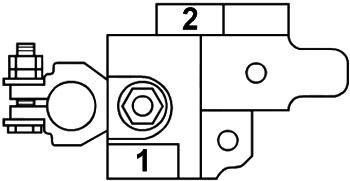
Fuse Connection
| Number | Amps [A] | Description |
|---|---|---|
| 1 | 120 | Complete electrical circuit, battery, starter motor, generator |
| 2 | 80 | P/S Control Module |