Fuse and relay box diagrams – Suzuki Celerio
Applies to vehicles manufactured over the years:
2014, 2015, 2016, 2017, 2018.
Instrument panel fuse box diagram
The fuse box is located under the instrument panel on the driver’s side. Remove the fuse box cover by pressing on both ends and removing the cover.
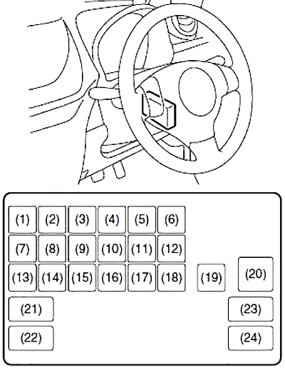
| Number | Amps [A] | Description |
|---|---|---|
| 1 | 10 | Stop Lights |
| 2 | 30 | Fan motor |
| 3 | 10 | STSIG |
| 4 | 15 | Accessory |
| 5 | 10 | Rear fog light |
| 6 | 10 | Rear Light |
| 7 | 10 | Backup Light |
| 8 | 10 | ABS |
| 9 | 10 | Counter |
| 10 | 15 | Ignition Coil |
| 11 | 20 | Window Washer |
| 12 | 10 | IG2 SIG |
| 13 | 10 | IG1 SIG |
| 14 | 10 | Airbag |
| 15 | 20 | Window Timer |
| 16 | 20 | Door Lock |
| 17 | 15 | Horns and hazard warning lights |
| 18 | 20 | Rear fog |
| 19 | 15 | Dome light |
| 20 | 30 | Supply of windows |
| 21 | 7,5 | ACC 2 |
| 21 | CNG (compressed natural gas) | |
| 22 | 15 | Radio 2 |
| 23 | – | ACC 2 (compressed natural gas) |
| 24 | – | Not used |
Diagram of the fuse box in the engine compartment
The main fuse, primary fuses, and some individual fuses are located in the engine compartment. If the main fuse blows, no electrical components will work. If the main fuse blows, no electrical components in the corresponding load group will operate.
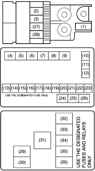
To remove a fuse, use the fuse puller located on the fuse box. The amperage of each fuse is shown on the back of the fuse box cover.
| Number | Amps [A] | Description |
|---|---|---|
| 1 | 80 | FL1 (PETROL) |
| 120 | FL1 (DIESEL) | |
| 2 | 50 | FL5 (PETROL) |
| 40 | FL5 (DIESEL) | |
| 3 | 50 | FL4 |
| 10 | 40 | Engine ABS |
| 11 | 40 | T/M Pump (gasoline) |
| 40 | IGN2 (DIESEL) | |
| 12 | 40 | Power steering |
| 13 | 20 | Front fog light |
| 14 | 7,5 | T/M 2 (gasoline), CNG (compressed natural gas) valve |
| 25 | F/P (DIESEL) | |
| 15 | 30 | Ignition Switch |
| 16 | 10 | Air Compressor |
| 17 | 15 | FI (BENZINE) |
| 30 | FI (DIESEL) | |
| 18 | 10 | T/M (PETROL) |
| 10 | EPI (DIESEL) | |
| 19 | 15 | Lighthouse (right) |
| 20 | 25 | ABS control module |
| 21 | 15 | Headlight (left) |
| 22 | 30 | Starting the engine |
| 23 | 30 | Radiator Fan |
| 27 | 80 | FL3 (PETROL) |
| 100 | FL3 (DIESEL) | |
| 28 | 80 | FL2 (PETROL) |
| 100 | FL2 (DIESEL) | |
| 29 | 20 | Glow plug |
| 30 | 20 | Glow plug 2 |
| 32 | – | Not used |
| 33 | 15 | FI2 |
| 34 | 20 | INJ DRV |
| 35 | – | Not used |
| 36 | – | Not used |
| 4 | Front fog light relay | |
| 5 | Glow plug relay | |
| 6 | CNG (compressed natural gas) valve relay | |
| 7 | Air Compressor Relay | |
| 8 | Reservation courier | |
| 9 | Relay F/P | |
| 24 | FI main relay (gasoline) | |
| Glow plug 2 (DIESEL) | ||
| 25 | Starter Relay | |
| 26 | Radiator Fan Relay | |
| 31 | FI main relay | |