Fuse diagrams and relay boxes – Suzuki Alto 800, K10
Applies to vehicles manufactured over the years:
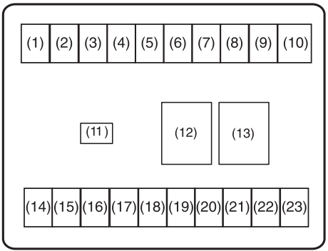
Diagram of the fuse box in the passenger compartment
The fuse box is located under the instrument panel on the driver’s side.
| Number | Amps [A] | Description |
|---|---|---|
| 1 | 10 | IG2 SIG |
| 2 | 15 | Cleaners |
| 3 | – | Not used |
| 4 | 7,5 | Automated manual transmission 2 (if equipped) |
| 5 | 30 | Fan motor |
| 6 | 10 | Stop the light |
| 7 | 10 | Rear light |
| 8 | 15 | Audio |
| 9 | 20 | Door Lock |
| 10 | – | Not used |
| 11 | 15 | Accessory |
| 12 | – | Not used |
| 13 | 30 | Supply of windows |
| 14 | 15 | Ignition switch |
| 15 | 10 | Direction indicators |
| 16 | 10 | Counter |
| 17 | 7,5 | Airbag |
| 18 | 7,5 | IG1 SIG |
| 19 | – | Not used |
| 20 | – | Not used |
| 21 | 30 | Power steering |
| 22 | 30 | SIG ST |
| 23 | 15 | Horn and hazard lights |
Diagram of the fuse box in the engine compartment
The main fuse, primary fuses, and some individual fuses are located in the engine compartment. If the main fuse blows, no electrical components will work. If the main fuse blows, no electrical components in the corresponding load group will operate.
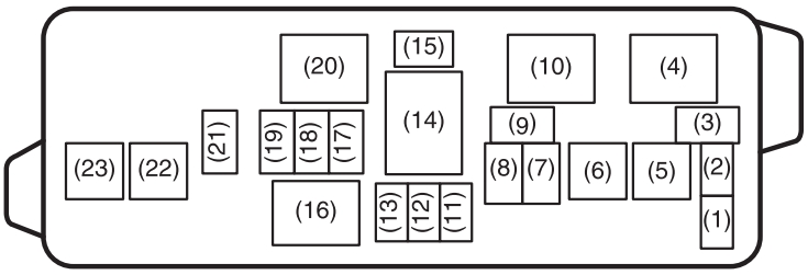
To remove a fuse, use the fuse puller located on the back of the fuse box cover. The amperage of each fuse is shown on the back of the fuse box cover.
| Number | Amps [A] | Description |
|---|---|---|
| 1 | – | Not used |
| 2 | – | Not used |
| 3 | 10 | Front fog lamps |
| 5 | 50 | Ignition switch |
| 6 | 50 | Battery 1 |
| 7 | 15 | Headlight (left) |
| 8 | 15 | Lighthouse (right) |
| 9 | 7,5 | CNG (if equipped) |
| 11 | – | Not used |
| 12 | – | Not used |
| 13 | – | Not used |
| 14 | 80 | All electric charge |
| 15 | – | Not used |
| 17 | 30 | Radiator Fan |
| 18 | 15 | Fuel injection |
| 19 | 10 | A/C Compressor |
| 21 | 7,5 | Automated manual transmission (if equipped) |
| CNG Valve (if equipped) | ||
| 22 | 40 | Automated manual gearbox pump (if equipped) |
| 23 | 30 | Accumulator 2 |
| 4 | A/C compressor relay | |
| 10 | Radiator Fan Relay | |
| 16 | Main relay | |
| 20 | Fuel Pump Relay | |