Skoda Yeti (2013) – fuse box diagram
Year of manufacture: 2013.
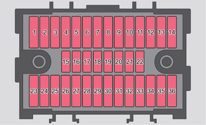
Lighter fuse (electrical outlet) in Skoda Yeti (2017). Are fuses #26 (starter power outlet) and #30 (front and rear lighters) in the fuse box on the dashboard.
| Fuse Color | Amps [A] |
|---|---|
| light brown | 5 |
| dark brown | 7,5 |
| red | 10 |
| blue | 15 |
| yellow | 20 |
| white | 25 |
| Green | 30 |
| Orange | 40 |
| red | 50 |
Instrument panel fuse box
| No. | Description |
| 1 | Transmission fan heating (diesel engine),
DQ200 automatic transmission controller |
| 2 | Towing device |
| 3 | Towing device |
| 4 | Indicator set;
Windshield wiper lever; Indicator Lever; Camera. |
| 5 | Air blower for heating;
Radiator Fan; Air conditioning system; Climatronic. |
| 6 | Rear wiper |
| 7 | Phone |
| 8 | Towing device |
| 9 | Vehicle Voltage Control Unit -[19659050
interior lighting, rear fog light |
| 10 | Rain sensor, light switch, diagnostic socket |
| 11 | Corner lights on the left |
| 12 | Corner lights on the right |
| 13 | Radio, switch for mobile navigation |
| 14 | Towing device |
| 15 | Light Switch |
| 16 | Haldex |
| 17 | Control unit for headlight adjustment and headlight rotation |
| 18 | Diagnostic Takeaway;
Engine controller; Brake sensor. |
| 19 | ABS, ESP control unit;
Tire pressure control switch; Parking assistance control unit; ROAD OFF mode switch; START STOP button. |
| 20 | Airbag switch and control unit |
| 21 | WIV;
Parking light; Tinted mirrors; Pressure sensor; Preparing for the phone; Air mass meter. |
| 22 | Indicator set;
Control unit for electromechanics power steering. |
| 23 | Central locking and hood cover |
| 24 | Rear power window |
| 25 | Rear window heating;
Parking lot heating and ventilation. |
| 26 | Power socket in the luggage compartment |
| 27 | Sliding electric roof;
Electric solar blind. |
| 28 | Fuel pump;
Injection valves. |
| 29 | Windscreen |
| 30 | Front and rear cigarette lighter |
| 31 | Headlight cleaning system |
| 32 | Front seat heating;
Controller for seat heating. |
| 33 | Heating;
Air conditioning; Climatronic; Remote control for parking heater. |
| 34 | Warning;
Spare Horn. |
| 35 | DQ200 Automatic Transmission Controller |
| 36 | CD/DVD |
Fuse box in engine compartment
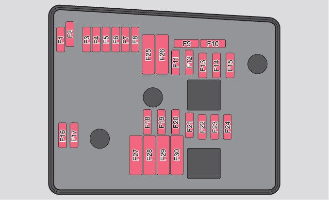
| No. | Description |
| F1 | Not assigned |
| F2 | Automatic Transmission Controller |
| F3 | Measuring circuit |
| F4 | ABS control unit |
| F5 | Automatic Transmission Controller |
| F6 | Instrument cluster;
Windshield wiper lever; Indicator Lever. |
| F7 | Supply terminal 15;
Starter. |
| F8 | Radio |
| F9 | Phone |
| F10 | Motor control unit |
| F11 | Additional control unit for heating and ventilation |
| F12 | Backplane control unit |
| F13 | Motor control unit |
| F14 | Ignition |
| F15 | Lambda Probe;
Fuel pump relay; Glow plug system. |
| F 16 | Vehicle voltage control unit,
Right headlight, right taillight. |
| F17 | Horn |
| F18 | Amplifier for digital sound processor |
| F19 | Cleaners |
| F20 | Fuel pressure control valve |
| F21 | Lambda sensor |
| F22 | Clutch pedal switch;
Brake pedal switch. |
| F23 | Coolant pump;
Charge pressure control solenoid valve; Radiator switching valve; High pressure fuel pump. |
| F24 | Activated carbon filter;
Exhaust gas recirculation valve; Radiator fan. |
| F25 | ABS control unit |
| F26 | Vehicle voltage control unit,
Left headlight, left tail light |
| F27 | Glow plug system |
| F28 | Windshield Heater |
| F29 | Indoor supply |
| F30 | Terminal X (a) |
| (a) In order not to unnecessarily discharge the battery during
starting the engine, the electrical components of the engine terminals are automatically switched off. |
|