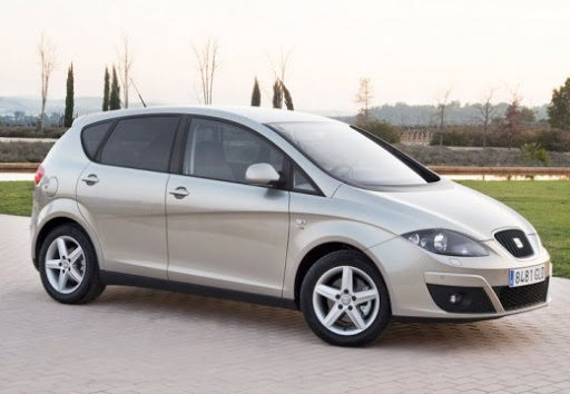
Seat Leon (2008) – Fuse box diagram
Year of manufacture: 2008
Fuses in the left side of the dashboard
| No. | Description | Amp [A] |
| 1 | Diagnostics;
Dashboard; Indicator lighting; Headlight Instrument Panel; Flow meter; Heated windshield wipers. |
10 |
| 2 | Engine controller;
ABS-ESP dashboard; Automatic transmission; Dashboard; Trailer dashboard; Light switch; Brake sensor; Power steering; Right and left headlights. |
5 |
| 3 | Airbag | 5 |
| 4 | Heating switch,
reverse gear; ASR-ESP switch; Phone; Nozzles; Electrochromic mirror; Bottom navigation. |
5 |
| 5 | Xenon Headlight Right | 5 |
| 6 | Left Xenon Headlight | 5 |
| 7 | – | – |
| 8 | – | – |
| 9 | – | – |
| 10 | – | – |
| 11 | – | – |
| 12 | Central locking system | 10 |
| 13 | Diagnosis;
Light switch; Rain sensor. |
10 |
| 14 | Automatic transmission;
Heating; ESP control panel; Automatic transmission lever. |
5 |
| 15 | Cable control unit | 7,5 |
| 16 | – | – |
| 17 | Alarm | 5 |
| 18 | – | – |
| 19 | – | – |
| 20 | – | – |
| 21 | Engine Management | 10 |
| 22 | Fan switch | 40 |
| 23 | Electric windows (front) | 30 |
| 24 | – | – |
| 25 | Rear window heating | 25 |
| 26 | Electric Rear Windows | 30 |
| 27 | Engine (fuel controller/pump relay) | 15 |
| 28 | Convenient Control | 25 |
| 29 | – | – |
| 30 | Automatic transmission | 20 |
| 31 | Vacuum Pump | 20 |
| 32 | – | – |
| 33 | Opening roof | 30 |
| 34 | Convenient Control | 25 |
| 35 | – | – |
| 36 | Headlight Washers | 20 |
| 37 | Heated seats | 30 |
| 38 | Engine Management | 10 |
| 39 | – | – |
| 40 | Fan switch | 40 |
| 41 | Rear wiper motor wiring,
instrument panel |
15 |
| 42 | 12 V socket;
Lighter. |
15 |
| 43 | Initial installation of the trailer bracket | 15 |
| 44 | Initial installation of the trailer bracket | 20 |
| 45 | Initial installation of the trailer bracket | 15 |
| 46 | – | – |
| 47 | Engine Management | 10 |
| 48 | Engine Management | 10 |
| 49 | – | – |
Fuse system, engine compartment, left side
| No. | Description | Amp [A] |
| 1 | Free | 30 |
| 2 | – | – |
| 3 | Cable control unit | 5 |
| 4 | ABS | 30 |
| 5 | AQ Gearbox | 15 |
| 6 | Combination/Directional Column | 5 |
| 7 | Ignition Key | 40 |
| 8 | Radio | 15 |
| 9 | Phone;
TomTom Navigation. |
5 |
| 10 | Engine Management | 5 |
| Engine Management | 10 | |
| 11 | – | – |
| 12 | Crossing | 5 |
| 13 | Supplying the gasoline injection module | 25 |
| Power to diesel injection module | 30 | |
| 14 | Coil | 20 |
| 15 | Engine Management | 5 |
| Fuel Pump Relay | 10 | |
| 16 | Proper Lighting | 30 |
| 17 | Horn | 15 |
| 18 | – | – |
| 19 | Pure | 30 |
| 20 | – | – |
| 21 | Lambda Sensor | 15 |
| 22 | Brake pedal;
Speed sensor. |
5 |
| 23 | Engine Management | 5 |
| Engine Management | 10 | |
| Engine Management | 15 | |
| 24 | ARF, change valve | 10 |
| 25 | ABS Pump | 40 |
| 26 | Illumination on the left | 40 |
| 27 | Engine Management | 40 |
| Engine Management | 50 | |
| 28 | – | – |
| 29 | Electric windows (front and rear) | 50 |
| Electric windows (front) | 30 | |
| 30 | Ignition Key | 40 |
Position in engine compartment: side box
| No. | Description | Amp [A] |
| B1 | Alternator <140 W. | 150 |
| Alternator> 140 W. | 200 | |
| C1 | Power steering | 80 |
| D1 | “30” multi-user supply;
Internal fuse box. |
100 |
| E1 | Fan <500 W;
Fan>500 W. |
50 |
| 80 | ||
| F1 | PTC
(electric supplemental air heating) |
80 |
| G1 | PTC
(electric supplemental air heating) |
40 |
| H1 | Central Control Lock | – |