Fuse diagrams and relay boxes – Nissan Quest
Applies to vehicles manufactured over the years:
2011, 2012, 2013, 2014, 2015, 2016.
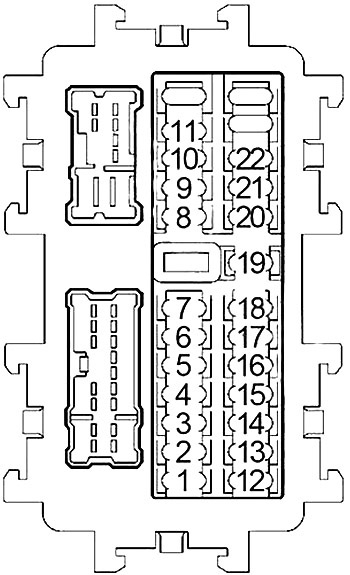
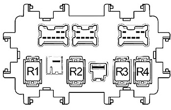
Instrument panel fuse box
The fuse panel is located behind the instrument panel cover. Pull to remove the fuse box cover (1).
Behind
| Number | Amps [A] | Opi |
|---|---|---|
| 1 | 15 | Heated seat switch |
| 2 | 10 | Airbag diagnostic sensor unit, passenger rating system control unit |
| 3 | 10 | Air conditioning booster, automatic tailgate control unit, sliding door control unit, power steering control unit, ASCD brake switch, stop light switch, exhaust/external odor detection sensor, electronically controlled engine mount solenoid valve, data link connector, AC 120 V main exhaust switch, steering angle sensor, ionizer, Tel adapter, AV control unit, rear viewfinder, automatic anti-spark interior mirror, surround view monitor control unit, rear air conditioning control unit |
| 4 | 10 | Combined counter, support relay |
| 5 | – | – |
| 6 | 15 | Smart key warning sound, data link connector, air conditioning amplifier, selective unlocking relay, automatic interior mirror to prevent dazzling, combination meter |
| 7 | 10 | Stop lamp switch, stop lamp relay, BCM (body control module) |
| 8 | 20 | Luggage storage power socket |
| 9 | 10 | Automatic tailgate control module, automatic tailgate warning buzzer, automatic sliding door warning buzzer, sliding door control module, seat power return control module, seat lock release actuator relay |
| 10 | 10 | BCM (body control module), seat memory switch, keyless remote access receiver |
| 11 | 10 | Transmission control module (TCM), pushbutton ignition switch |
| 12 | – | – |
| 13 | 10 | Outdoor mirror, air conditioning amplifier |
| 14 | – | – |
| 15 | 20 | Rear window defogger |
| 16 | – | – |
| 17 | – | – |
| 18 | – | – |
| 19 | 10 | A/C amplifier, audio, Tel adapter, multifunction switch, front display, AV control unit, satellite radio tuner, rear display, remote control switch for side mirrors |
| 20 | 20 | Front power socket |
| 21 | 15 | Front fan motor |
| 22 | 15 | Front fan motor |
| R1 | Ignition | |
| R2 | Rear window defogger | |
| R3 | Accessory | |
| R4 | Front Fan | |
Additional Fuse Holder
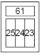
| Number | Amps [A] | Description |
|---|---|---|
| 23 | 15 | Rear blower relay |
| 24 | 15 | Rear blower relay |
| 25 | – | – |
| 61 | – | – |
Engine compartment
Remove the fuse box cover by pressing the tab (1).
Fuse Box #1
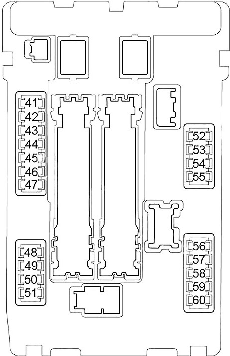


| Number | Amps [A] | Description |
|---|---|---|
| 41 | 15 | Fuel Pump Relay |
| 42 | 10 | Cooling fan relay 2, cooling fan relay 3 |
| 43 | 10 | Additional speed sensor, Transmission Control Module (TCM) |
| 44 | 10 | Injectors, engine control module (ECM) |
| 45 | 10 | ABS, switch BSW, BSW control unit, side radar |
| 46 | 15 | Fuel/air ratio sensor, heated oxygen sensor |
| 47 | 10 | Combination Switch |
| 48 | – | – |
| 49 | 10 | Air Conditioning Relay |
| 50 | 15 | Engine control module relay (VIAS control solenoid, intake valve control solenoid valve, EVAP canister vent control valve, condenser, ignition coils, engine control module, mass airflow sensor, EVAP canister volume control solenoid valve) |
| 51 | 15 | Throttle control motor relay |
| 52 | 10 | Front combination lights, front marker lights, signal lights |
| 53 | 10 | Rear combination lamps, license plate lamps, VDC switch, headlight aiming switch, glove box lamp, 120 volt AC main switch, auto door main switch, combination switch, hazard switch, air conditioning switch, gauge control switch, lighting control switch, BSW switch, automatic tailgate switch, CVT gear selector lighting, foot lamps, sliding door open/close switch, audio, heated seat switch, rear air conditioning control, map light, remote door mirror control switch, disc eject switch, multifunction switch, rear display |
| 54 | 10 | Left Headlight |
| 55 | 10 | Right headlight |
| 56 | 15 | Headlight Low-Left |
| 57 | 15 | Reflector low right |
| 58 | 15 | Front fog light |
| 59 | 10 | Daylight Continuous Relay |
| 60 | 30 | Front Wiper Relay |
Fuse box #2
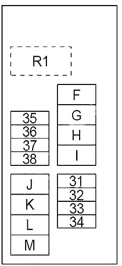


| Number | Amps [A] | Description |
|---|---|---|
| 31 | – | – |
| 32 | – | Trailer |
| 33 | 30 | Seatback power feedback control unit, seatback release actuator relay |
| 34 | 30 | Inverter Unit |
| 35 | 20 | Audio, AV control unit, satellite radio tuner, display (front, rear), room monitor control unit, Tel adapter module |
| 36 | – | – |
| 37 | 15 | Horn relay |
| 38 | 10 | Generator |
| F | 30 | ABS |
| g | 20 | ABS |
| h | 40 | Ignition relay (fuses: “1”, “2”, “3”, “4”), IPDM E/R, fuse: “6” |
| i | – | – |
| J | 40 | Automatic switch (automatic tailgate control unit), automatic switch (sliding door control unit, tailgate control unit) |
| K | 40 | Cooling fan relay 2, cooling fan relay 3 |
| L | 40 | BCM (body control module), automatic switch (driving positioner automatic control unit, driver’s seat control, lumbar support switch) |
| m | 40 | Cooling fan motor 1 |
| R1 | horn | |
Additional Fuse Holder
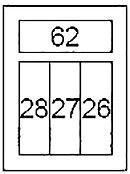


| Number | Amps [A] | Description |
|---|---|---|
| 26 | 15 | BOSE Amplifier |
| 27 | 15 | BOSE Amplifier |
| 28 | 15 | BOSE Amplifier |
| 62 | – | – |
Fuse Connection Block
Located on the “+” terminal of the battery.
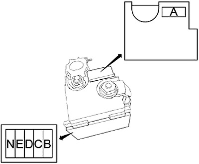


| Number | Amps [A] | Description |
|---|---|---|
| A | 250 | Generator, starter, fuse: “B”, “C”, “D” |
| b | 100 | Fuse: “F”, “G”, “H”, “J”, “K”, “L”, “M”, “32”, “33”, “34”, “35”, “37”, “38” |
| C | 60 | High beam relay (fuses: “54”, “55”), low beam relay (fuses: “56”, “57”), tail beam relay (fuses: “52”, “53”), fuse: “58 , “59”, “60” |
| D | 100 | Power steering control module |
| E | 80 | Ignition relay (fuses: “41”, “42”, “43”, “44”, “45”, “46”, “47”, “49”), fuse: “50”, “51” |
| n | 100 | Accessory relay (fuses: “19”, “20”), rear window defroster relay (fuses: “13”, “15”), front fan relay (fuses: “21”, “22”), fuse: “6” , “7”, “8”, “9”, “10”, “11”, “23”, “24” |

