Fuse diagrams and relay boxes – Nissan Quest
Applies to vehicles manufactured over the years:
2004, 2005, 2006, 2007, 2008, 2009.
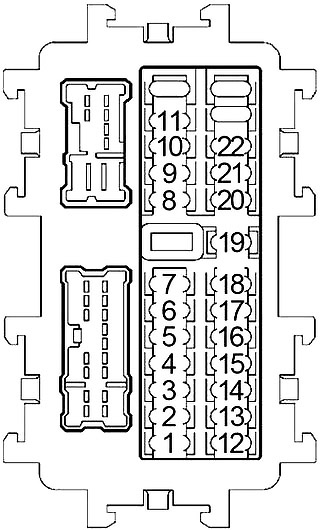
Instrument panel fuse box
The fuse panel is located behind the glove box in the instrument panel. Pull the eyepiece holder down to open (1), then pull the eyepiece holder (2) and remove to reveal the fuse panel.
Behind
| Number | Amps [A] | Description |
|---|---|---|
| 1 | 10 | Control unit adjustment pedal, stop light switch |
| 2 | 10 | Front fan motor relay, front air control |
| 3 | 15 | Body Control Module (BCM), automatic interior mirror to prevent dazzling |
| 4 | 10 | Audio, AV switch, display unit, display control unit, navigation control unit, DVD player, satellite radio tuner, body control module (BCM) |
| 5 | 15 | Front power socket 2, rear power socket (2nd row) |
| 6 | 10 | Remote control switch for exterior mirrors |
| 7 | – | – |
| 8 | 10 | Door mirror |
| 9 | 10 | Driver’s seat controller , diode 1 |
| 10 | 15 | Rear fan motor |
| 11 | 15 | Rear fan motor |
| 12 | 10 | Automatic Speed Control Device (ASCD) brake switch, data link connector, combination meter, heated seat relay, neutral parking position switch, display, steering angle sensor, control unit display, Navi control unit, tailgate control unit, sliding door control unit, sonar control unit, daytime running lights, hands-free phone |
| 13 | 10 | Airbag diagnostic sensor unit, passenger rating system control unit |
| 14 | 10 | Combination meter, neutral parking position switch, automatic dimming of the interior mirror |
| 15 | – | – |
| 16 | 10 | Injectors, body control module (BCM), engine control module (ECM) |
| 17 | 10 | Navi control unit, tailgate control unit, sliding door control unit, driver’s seat control unit, seat memory switch, automatic drive positioning control unit |
| 18 | 15 | Subwoofer |
| 19 | 15 | Transmission control module (TCM), A/V switch, dial, steering angle sensor, combination meter, electronically controlled engine front mount, control dial, key switch, front air control |
| 20 | 10 | Stop lamp switch |
| 21 | 15 | Front power socket 1, rear power socket (Cargo) |
| 22 | 15 | Fuel cap opening relay, DVD player |
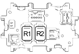
| R1 | Blower | |
| R2 | Accessory | |
Engine compartment fuse box #1
The fuse block is located near the windshield washer fluid reservoir.
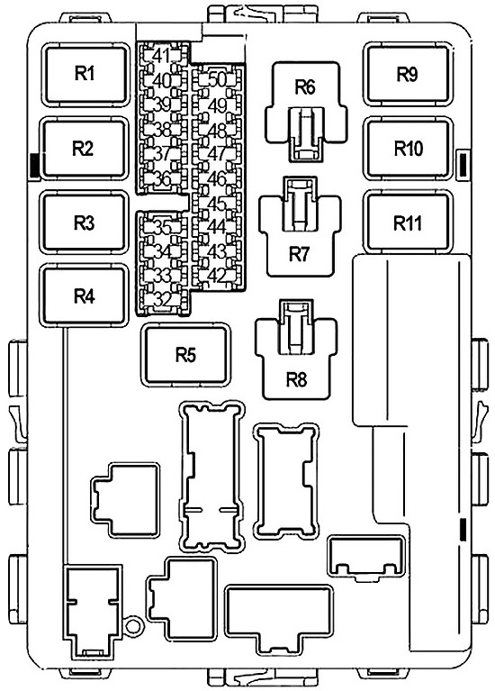
| Number | Amps [A] | Description |
|---|---|---|
| 32 | 20 | Rear window defroster relay |
| 33 | 10 | Air Conditioning Relay |
| 34 | 15 | IPDM E/R Processor |
| 35 | 15 | Engine control module (ECM), ECM relay, NATS antenna amplifier |
| 36 | 15 | Right reflector, LED 3 |
| 37 | 20 | Rear window demist relay |
| 38 | 10 | Daytime running light left, daytime running light control unit |
| 39 | 30 | Front Wiper Relay |
| 40 | 10 | Daytime running light right, daytime running light relay, diode 3 |
| 41 | 15 | Tail lamp relay, corner lamp relay, IPDM E/R processor |
| 42 | 10 | Heating pump relay |
| 43 | 15 | Front fog light relay |
| 44 | 15 | Throttle control motor relay |
| 45 | 15 | Left headlight, daytime running lights |
| 46 | 15 | Air flow sensor, heater oxygen sensor |
| 47 | 10 | Combination switch (front wiper and washer, rear wiper and washer) |
| 48 | 10 | Transmission control module (TCM), speed sensor, turbine speed sensor, A/T PV IGN relay |
| 49 | 10 | ABS |
| 50 | 15 | Fuel pump relay |
| R1 | Motor control module | |
| R2 | Highlights | |
| R3 | Low beam | |
| R4 | Starter | |
| R5 | Ignition | |
| R6 | Cooling fan (№1) | |
| R7 | Cooling fan (№3) | |
| R8 | Cooling fan (№2) | |
| R9 | Throttle control motor | |
| R10 | Fuel Pump | |
| R11 | Front fog light | |
Engine compartment fuse box 2
It is near the battery. Remove the fuse box cover by pressing the latch and lifting the cover.
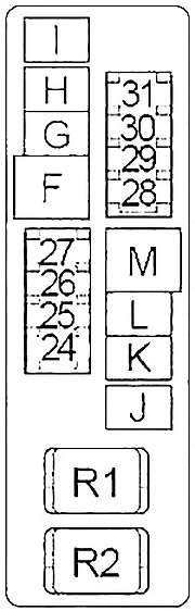
| Number | Amps [A] | Description |
|---|---|---|
| 24 | 20 | Trailer Towing Set |
| 25 | 15 | Horn relay |
| 26 | 10 | Generator |
| 27 | 15 | Heated seat relay |
| 28 | 20 | Front fan motor relay |
| 29 | 15 | Daytime Running Lights |
| 30 | 20 | Front fan motor relay |
| 31 | 20 | Audio, BOSE amplifier, satellite radio tuner |
| F | 40 | ABS |
| g | 40 | Cooling Fan Relay 2 |
| h | 40 | Cooling fan relay 1, cooling fan relay 3 |
| i | 40 | Circuit breaker 1 (automatic sliding door closing system, electrical outlet ) |
| J | 50 | Body Control Module (BCM) |
| K | 40 | Ignition Switch |
| L | 40 | ABS |
| m | 40 | Breaker 2 (adjustable foot pedal system, automatic drive positioner, automatic sliding door closing system, electric seat ) |
| R1 | horn | |
| R2 | Front fan motor | |
Fuse Connection Block
You are in battery + terminal.
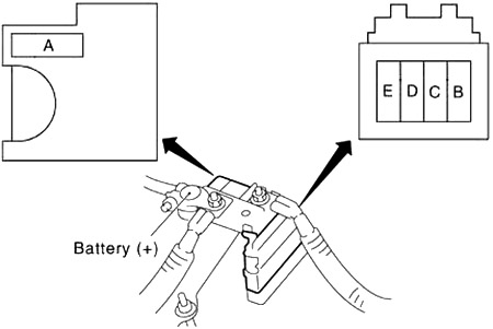
| Number | Amps [A] | Description |
|---|---|---|
| A | 140 | Generator, fuse: “D”, “E”. |
| b | 80 | Accessory relay (fuses: “4”, “5”, “6”), rear fan motor relay (fuses: “10”, “11”), fuse: “3”, “17”, “18”, “19”, “20”, “21”, “22” |
| C | 60 | Ignition relay (Fuses: “42”, “46”, “47”, “48”, “49”, “50”), Fuses: “33”, “34”, “35”, “37” |
| D | 80 | High beam relay (fuses: “38”, “40”), low beam relay (fuses: “36”, “45”), Fuses: “32”, “39”, “41”, “43”, “44 “ |
| E | 100 | Fuse: ‘F’, ‘G’, ‘H’, ‘J’, ’24’, ’25’, ’26’, ’27 |