Nissan Note (2004-2013) – fuse box diagram
Year of manufacture: 2004, 2005, 2006, 2007, 2008, 2009, 2010, 2011, 2012, 2013.
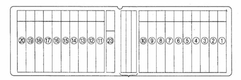
Lighter fuse (electrical outlet) on Nissan Note (2004-2013). Is fuse 20 in the fuse box.
Passenger compartment
LHD
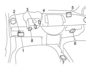
RHD

| No. | Description |
| 1 | Fuse box |
| 2 | Door Lock Relay
(with intelligent key system). |
| 3 | Antenna amplifier
Nissan Anti-Theft System (NATS). |
| 4 | Intelligent Key Unit
(with Intelligent Key system). |
| 5 | Body Control Module (BCM) |
| 6 | Gearbox control module |
| 7 | Diagnostic sensor module
airbag. |
| 8 | ESP Control Unit |
Passenger compartment fuse box

| No. | Amps [A] | Description |
| 1 | 10 | Additional Retention System |
| 2 | 10 | Electric power steering system;
Ignition relay; Fuel pump relay; Nissan anti-theft system; Intelligent key system; Body Control Module (BCM). |
| 3 | 10 | Indicator set;
Warning lights; Lighting; Warning alarm; Charging system. |
| 4 | 15 | Washers |
| 5 | 10 | Denormalization of the mirror |
| 6 | 10 | Audio;
Intelligent key system; Nissan anti-theft system; External mirror. |
| 7 | 10 | Body Control Module (BCM) |
| 8 | 10 | Central locking;
Remote control system with multiple remote controls; Intelligent key system; Aftermarket alarm – pre-wiring; Warning sound; Nissan anti-theft system. |
| 9 | 10 | Traffic light;
Brake switch; Anti-lock braking system; Electronic stabilization system; Warning lights; Intelligent key system. |
| 10 | – | – |
| 11 | – | – |
| 12 | 10 | Interior lamp;
Remote control system with multiple remote controls; Lighting; Cosmetic mirror and lamps in the trunk; Rain sensor; Warning sound. |
| 13 | – | – |
| 14 | 10 | Dashboard backlighting;
OBD II (on-board computer diagnostics); Intelligent key system; Direction indicators and warning lights. |
| 15 | 15 | Air Conditioning |
| 16 | 10 | PTC Heater |
| 17 | 15 | Air Conditioning |
| 18 | 15 | Rear power point |
| 19 | 10 | Heated seat |
| 20 | 15 | Front power point
(lighter). |
| Relay | ||
| R1 | Fan motor | |
| R2 | Accessory | |
Engine compartment
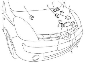
| No. | Description |
| 1 | Fuse Box (IPDM E/R) |
| 2 | PTC Relay Box |
| 3 | Additional fuse box |
| 4 | K9K: fuse switch box |
| 5 | Fuse connection bracket |
| 6 | LHD: ABS actuator and electrical unit |
| 7 | RHD: ABS actuator and electrical unit |
| 8 | Windshield wiper motor |
| 9 | Engine Control Module (ECM) |
Engine compartment fuse box

| No. | Amps [A] | Description |
| 41 | – | – |
| 42 | – | – |
| 43 | 10 | Right headlights (high beam);
Daytime running light system; Automatic light control. |
| 44 | 10 | Left headlights (high beam);
Daytime running light system; Automatic light control. |
| 45 | 10 | Backlight;
Parking light; Automatic light control; Lighting. |
| 46 | 10 | Backlight;
Parking light; Automatic light control; Feature; Lighting. |
| 47 | – | – |
| 48 | 20 | Front windshield wiper and washer
(with rain sensor) |
| 49 | 15 | Left headlights (low beam);
Daytime running light system; Automatic light control. |
| 50 | 15 | Right headlights (dipped beam);
Daytime running light system; Automatic light control. |
| 51 | 10 | Air Conditioning |
| 52 | – | – |
| 53 | – | – |
| 54 | – | – |
| 55 | 15 | Rear window defroster, fuse “5 |
| 56 | 15 | Rear window defroster, fuse “5 |
| 57 | 15 | CR, HR:
Fuel Pump Relay |
| 58 | 10 | A/T vehicle speed sensor (speed sensor);
A/T fluid temperature sensor and MTC power supply; Main power supply and ground circuit; Turbine speed sensor. |
| 59 | 10 | Anti-lock braking system;
Electronic stabilization program. |
| 60 | 10 | Parking position/neutral position switch;
Undetectable components; Startup system; Backup light; A/T indicator light; Rear wiper and washer. |
| 61 | 20 | CR, HR:
Throttle control motor relay |
| 62 | 20 | Relay motor control module;
Main power supply and ground circuit; Mass airflow sensor; Crankshaft position sensor (CKPS); Camshaft position sensor (FAZA); Volume control solenoid valve EVAP fuel vapor exhaust vent; Ignition system; Solenoid control valve Intake valve timing; Aftermarket alarm – pre-wiring; Fuel injector; Camshaft position sensor; Fuel flow adjustment element; Solenoid valve Turbocharger; Brake switch; ECM backup power supply (CR motor). |
| 63 | 10 | CR, HR:
Front heated oxygen sensor; Rear heated oxygen sensor; Fuel injection system function. |
| 64 | 10 | CR, HR:
Fuel injection system function; Fuel injector. |
| 65 | 20 | Front fog light |
| Courier | ||
| R1 | Rear window defogger | |
| R2 | Engine control module (ECM) | |
| R3 | Low beam | |
| R4 | Front fog light | |
| R5 | Starter | |
| R6 | – | |
| R7 | Cooling fan (high) | |
| R8 | Cooling fan (low) | |
| R9 | Ignition | |
Additional engine compartment fuse box
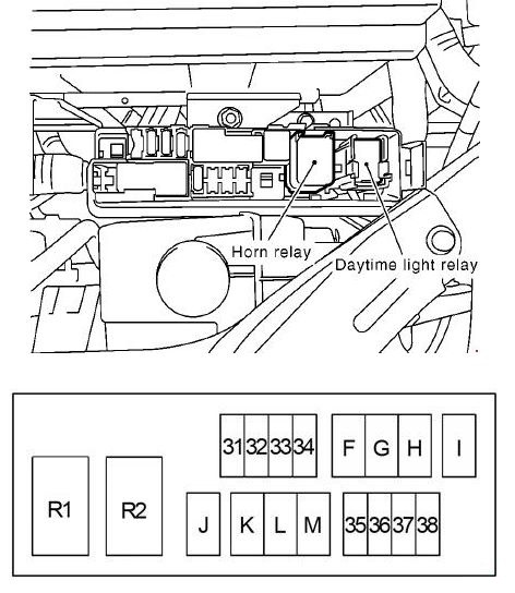
| No. | Amps [A] | Description |
| 31 | – | – |
| 32 | – | – |
| 33 | – | – |
| 34 | 15 | Sound System |
| 35 | 10 | Horn |
| 36 | 10 | CR, HR:
Charging system |
| 37 | 10 | Daylighting system |
| 38 | – | – |
| F | 40 | Anti-lock braking system;
Electronic stabilization program. |
| G | 40 | Low Level Relay
cooling fan; high cooling fan relay. |
| H | 40 | Ignition Switch |
| I | 40 | PTC Heater |
| J | 40 | Supply of windshields;
Body Control Module (BCM). |
| K | 30 | Anti-lock braking system;
Electronic stabilization program. |
| L | 30 | Headlight Washer |
| M | 60 | Electrically controlled system
power steering. |
| Courier | ||
| R1 | Daylight | |
| R2 | Horn | |
Fuse Junction Box (K9K)

| No. | Amps [A] | Description |
| N | 80 | PTC Heater |
| O | 60 | Quick Glow System |
| P. | 80 | PTC Heater |
Fuse connection bracket

| No. | Amps [A] | Description |
| A | 80 | CR:
charging system, starting system, fuses “B”, “C |
| 140 | RH:
charging system, starting system, fuses “B”, “C |
|
| 250 | K9K:
Charging system, fuses “B”, “C”, “N”, “O”, “P” |
|
| B | 80 | CR, K9K:
Fuses: “35”, “36”, “37”, “38”, “F”, “G”, “H”, “I”, “J”, “K”, “L”, “M “ |
| 100 | RH:
Fuses: “35”, “36”, “37”, “38”, “F”, “G”, “H”, “I”, “J”, “K”, “L”, “M” |
|
| C | 80 | RH headlight high level relay (fuse “43”);
Reflector LH high-level relay (fuse “44”); Tail lamp relay (fuses “45”, “46”); Low headlight relay (fuses “49”, “50”); Front fog light relay (fuse “65”); Fuses “48”, “51”. |
| D | 60 | Ignition Relay
(Front windshield wiper main relay, high/low wiper relay, “57”) (CR, HR), ’58’, ’59’, ’60’, ’63’ (CR, HR), ’64’ (CR , HR)) Fuel pump relay (CR, HR); Fuses “55”, “56”, “61”, “62”. |
| E | 80 | Accessory relay (fuses “18”, “19”, “20”),
Blower motor relay Fuses “15”, “16”, “17”, “1”, “2”, “3”, “4”. Fuses “5”, “6”, “7”, “8”, “9”, “12”, “14”. |
| Gasoline:
1.4 l – CR14DE, 1,; l – HR16DE; Diesel: 1.5 l – K9K. |
||