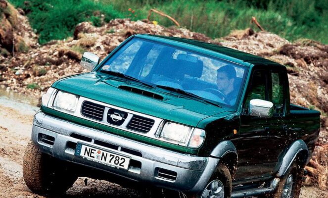
Nissan Navara (1997-2004) – Fuse box diagram
Year of manufacture: 2003, 2004, 2005, 2006, 2007, 2008, 2009, 2010.
Lighter fuse (electrical outlet) in Nissan Navara (1997-2004). Is fuse F17 in the fuse box.
Passenger compartment fuse box
Located on the right side of the glove box, behind the protective cover.


| No. | Amps [A] | Description |
|---|---|---|
| 1 | Ignition relay 1 main circuits | |
| 2 | Auxiliary ignition circuit relay | |
| 3 | Relay 2 main ignition circuits | |
| 4 | Window Lifter Relay | |
| 5 | Thermal fuse (central locking) | |
| F1 | 20A | Rear window defogger |
| F2 | 10 A | Anti-lock braking system (ABS);
Brake lights. |
| F3 | 10 A | Interior lighting lamps;
Fog lamps. |
| F4 | – | – |
| F5 | 10 A | Light and alarm switch |
| F6 | 10 A | Air conditioning;
Anti-theft system; Audio antenna; Automatic transmission control system; Clock; Diagnostic connector; Immobilizer; Dashboard; Central locking by remote control; Car speed sensor. |
| F7 | 10 A | Audio system;
Audio Antenna. |
| F8 | 10 A | Seat warmer |
| F9 | – | – |
| F10 | 10 A | Light and alarm switch |
| F11 | 10 A | SRS system (airbag);
Automatic transmission system; Charging system; Daytime running lights; Faults in the glow plug motor management system; Immobilizer; Dashboard; Counters and indicators; Reversing lights; Car speed sensor; Direction indicators. |
| F12 | 10 A | ABS system;
Audible warning signal / buzzer; Automatic transmission; Diagnostic connector; Daytime running light; Low beam headlights; High beam headlights; Power windows; Engine heating switch; Side mirror heater; Rear window defogger; Remote control system with centralized locking. |
| F13 | 10 A | Additional idle air control valve (some models);
Air conditioning system; Cooling fan relay. |
| F14 | – | – |
| F15 | 15A | Heating / air conditioning |
| F 16 | 15A | Heating / air conditioning |
| F17 | 15A | Lighter |
| F18 | 20A | Headlight Washers |
| F19 | 10 A | Heated side mirror heater |
| F20 | 10 A | Daytime running light;
Electronic engine control unit (start signal). |
| F21 | 10 A | Motor control system;
Immobilizer. |
| F22 | 15A | Motor control system;
Fuel pump relay. |
| F23 | 15A | Engine Management System (ZD30) |
| F24 | 10 A | Airbag |
| F25 | 10 A | Engine Management |
| F26 | 20A | Windshield Wiper and Washer |
| F27 | 10 A | Audible warning / buzzer;
Headlight corrector, front / rear (left); Left license plate light; Switch illumination. |
| F28 | 10 A | Front/rear (right) dimensions;
Right license plate light. |
| F29 | – | – |
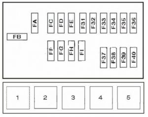
Fuse panel in engine compartment
The fuse panel is located in the engine compartment (right side).


| No. | Amps [A] | Description |
|---|---|---|
| FA | 80A / 100A | Battery power distribution (80A-Petrol, 100A-Diesel) |
| FB | 60A / 80A | Glow plugs (60A-YD engine, 80A-excluding YD engine) |
| FC | 40A | Central locking;
Electric windows. |
| FD | 30A | Cooling fan motor |
| FE | – | – |
| FF | 40A | Ignition Switch |
| FG | 30A | Antilock Braking System (ABS) |
| FH | 30A | Antilock Braking System (ABS) |
| FI | 30A | Combination switch, daytime running lights |
| F31 | 10 A | Charging system |
| F32 | 10 A | Horn |
| F33 | 10 A | Engine management system;
Immobilizer (gasoline). |
| F34 | – | – |
| F35 | 10 A | Engine Management System (Diesel) |
| F36 | 20A | Engine management system;
Immobilizer (Diesel). |
| F37 | 15A | Combination switch;
Daytime running lights; Dipped/driving lights; Headlights; Fog light(s). |
| F38 | 15A | Combination switch;
Daytime running lights; Dipped/driving lights; Headlights. |
| F39 | 10 A | Public Address System |
| F40 | 15A | Fog lamps (some models) |
| Relay | ||
| 1 | Cooling Fan Relay | |
| 2 | A/C compressor solenoid clutch relay | |
| 3 | Horn relay | |
| 4 | Relay start lock (“P” / “N”) | |
| 5 | Engine Management Relay | |


