Fuse diagrams and relay boxes – Nissan Murano Z51
Applies to vehicles manufactured over the years:
2009, 2010, 2011, 2012, 2013, 2014.
Cigarette lighter (socket) fuses in the Nissan Murano are fuses 18 (cigarette lighter) and 20 (front socket) in the fuse box on the instrument panel.
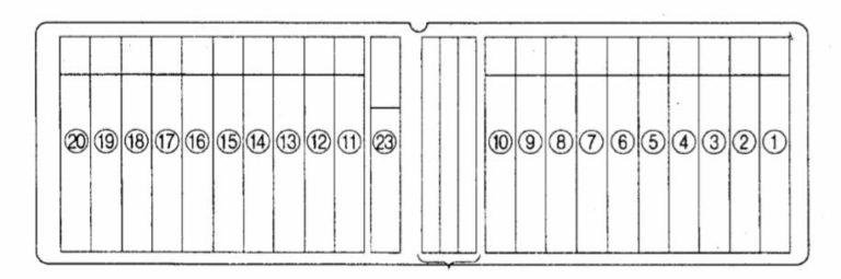
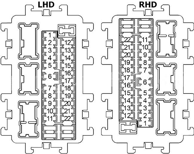
Instrument panel fuse box
The fuse box is located behind the instrument panel cover on the driver’s side.
Behind
| Number | Amps [A] | Description |
|---|---|---|
| 1 | 15 | Front heated seat |
| 2 | 10 | Airbag diagnostic sensor unit |
| 3 | 10 | Automatic tailgate control unit, ASCD brake switch, stop light switch, headlight aiming motor, electronically controlled engine mount control solenoid valve, data link connector, steering angle sensor, air conditioning amplifier, heated seat relay, power steering control unit, BCM (Body Control Module), Navi control unit, optional connector, video splitter, automatic anti-obstruction interior mirror, automatic leveling control unit |
| 4 | 10 | Combination counter, spare bulb relay |
| 5 | 10 | Fuel cap opening relay |
| 6 | 10 | Smart key warning buzzer, data link connector, air conditioning amplifier, automatic tailgate control unit, automatic tailgate warning buzzer, vehicle tilt sensor, siren control unit, rear backrest power return control unit, light and rain sensor |
| 7 | 10 | Stop light switch, BCM (body control module) |
| 8 | – | Not used |
| 9 | 10 | Key socket, safety light, ignition button |
| 10 | 10 | Seat memory switch, BCM (body control module) |
| 11 | 10 | Combination counter, transmission control module (TCM) |
| 12 | – | Not used |
| 13 | 10 | Outdoor mirror defogger, air conditioner amplifier |
| 14 | 20 | Rear window defogger |
| 15 | 20 | Rear window defogger |
| 16 | – | Not used |
| 17 | – | Not used |
| 18 | 15 | Lighter socket |
| 19 | 10 | Audio, front display, air conditioning amplifier, rear display, Navi control unit, DVD player, video distributor, camera control unit, power take-off relay, BCM (body control module), multifunction switch, door mirror remote control switch |
| 20 | 15 | Front power socket |
| 21 | 15 | Fan motor |
| 22 | 15 | Fan motor |
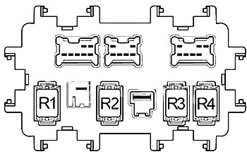
| Relay | ||
| R1 | Ignition | |
| R2 | Rear window defogger | |
| R3 | Accessory | |
| R4 | Front Fan |
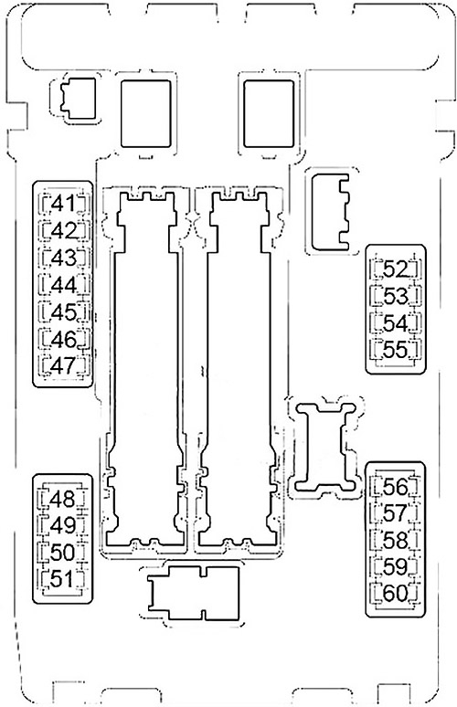
Fuse box in engine compartment
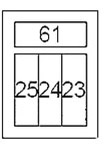
| Number | Amps [A] | Description |
|---|---|---|
| 23 | 15 | BOSE Amplifier |
| 24 | 15 | BOSE Amplifier |
| 25 | 15 | Subwoofer |
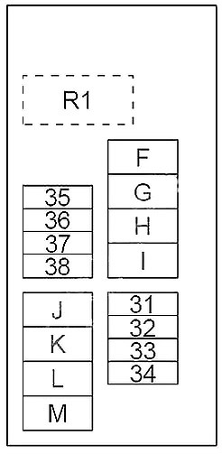
| 31 | 20 | Optional connector |
| 32 | 15 | Rear backrest power feedback control unit |
| 33 | 20 | Power socket relay |
| 34 | 20 | Seat heating relay |
| 35 | 20 | Audio, front display, rear display, Navi control unit, DVD player, video distributor, camera control unit |
| 36 | 15 | 4WD control unit |
| 37 | 10 | Horn relay |
| 38 | 15 | Generator, vehicle safety horn relay |
| F | 40 | ABS |
| g | 40 | ABS |
| h | – | Not used |
| i | 50 | Ignition relay (fuses 1, 2, 3, 4), IPDM E/R |
| J | 40 | Automatic switch (automatic tailgate control module) |
| K | 40 | Cooling fan relay 2, cooling fan relay 3 |
| L | 40 | BCM (body control module), automatic switch (automatic driving positioner control unit, driver’s seat control, lumbar support switch) |
| m | 40 | Cooling fan motor 1 |
| 41 | 15 | Fuel pump relay |
| 42 | 10 | Cooling fan relay 2, cooling fan relay 3 |
| 43 | 10 | Additional speed sensor, Transmission Control Module (TCM) |
| 44 | 10 | Injectors, engine control module (ECM) |
| 45 | 10 | ABS, 4WD control unit |
| 46 | 15 | Fuel/air ratio sensor, heated oxygen sensor |
| 47 | 10 | Combination Switch |
| 48 | 10 | Flywheel lock relay |
| 49 | 10 | Air Conditioning Relay |
| 50 | 15 | Engine control module relay (VIAS control solenoid, intake valve control solenoid, condenser, ignition coils, engine control module, mass air flow sensor, EVAP canister purge volume control solenoid valve) |
| 51 | 15 | Throttle control motor relay |
| 52 | 10 | Parking Lamp |
| 53 | 10 | Rear combination lamp, license plate lamp, center ambient lamp, map lamp, heated front seat switch, heated rear seat switch, optional connector, ESP switch, 4WD lock switch, ashtray light, group light, glove box light, combination switch (spiral) Cable), hazard switch, control unit light, automatic tailgate switch, automatic 8ack door switch, front power return switch, multifunction switch, Navi control unit, DVD player, exterior mirrors remote control switch, front door handle light, automatic leveler – control unit |
| 54 | 10 | High beam headlight (left) |
| 55 | 10 | High beam headlight (right) |
| 56 | 15 | Low beam (left) |
| 57 | 15 | Low beam (right) |
| 58 | 15 | Front fog light relay |
| 59 | 10 | Daylight Continuous Relay |
| 60 | 30 | Front Wiper Relay |
| 61 | 40 | Headlight Washer Relay Relay |
| R1 | – | Horn relay |
Fuse block (main fuses)
Located on the positive terminal of the battery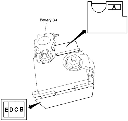
| Number | Amps [A] | Description |
|---|---|---|
| A | 250 | Generator, starter, fuses B, C |
| B | 100 | Fuses F, G, I, J, K, L, M, 31, 32, 33, 34, 35, 36, 37, 38 |
| C | 60 | High beam relay (fuses 54, 55), low beam relay (fuses 56, 57), tail beam relay (fuses 52, 53), fuses 58, 59, 60 |
| D | 100 | Accessory relay (fuses 18, 19, 20), rear window defroster relay (fuses 13, 14, 15), fan relay (fuses 21, 22), fuses 5, 6, 7, 9, 10, 11, 23, 24, 25, 61 |
| E | 80 | Ignition relay (fuses 41, 42, 43, 44, 45, 46, 47), fuses 48, 49, 50, 51 |