Fuse diagrams and relay boxes – Nissan Altima SE, S/S, SE-R (L31)
Applies to vehicles manufactured over the years:
2002, 2003, 2004, 2005, 2006.
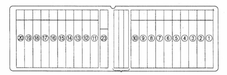
Passenger compartment fuse box
The fuse panel is located behind the instrument panel cover on the driver’s side. Pull the fuse box cover to remove it.
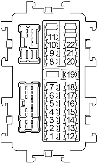
Rear
| Number | Amps [A] | Description |
|---|---|---|
| 1 | 10 | Engine control module, injectors, immobilizer control unit (2001-2002), body control module (BCM (2003-2006)) |
| 2 | – | – |
| 3 | – | – |
| 4 | – | – |
| 5 | 15 | Power socket |
| 6 | 10 | 2001-2002: Audio, body control module (BCM), remote control switch for exterior mirrors |
| 10 | 2003-2006: Audio, body control module (BCM), exterior mirror remote control switch, AV switch, combination meter, display control unit, NAVI control unit, triple meter, satellite radio tuner | |
| 7 | 15 | Lighter |
| 8 | 10 | Outside mirror (left, right) |
| 9 | 10 | Engine control module (2001-2002), daytime running lights |
| 10 | 15 | Blower motor, automatic air conditioning booster (2001-2002), front air control (2003-2006) |
| 11 | 15 | Blower motor, automatic air conditioning booster (2001-2002), front air control (2003-2006) |
| 12 | 10 | 2001-2002: Automatic speed control device (ASCD) brake switch, data link connector, daytime running lights, starter relay, shift lock control unit, automatic air conditioning amplifier, temperature control amplifier, body control module (BCM), air conditioning control unit, combination switch, heated seat relay, rear window defroster |
| 10 | 2003-2006: automatic speed control device (ASCD) brake switch, ASCD clutch switch, body control module (BCM), display control unit, data link connector, daytime running lights, front air control, front seat relay, NAVI control unit, neutral parking position switch, rear window defroster relay, starter relay, gear lock control unit | |
| 13 | 10 | Airbag diagnostic sensor unit, passenger rating system control unit (2003-2006) |
| 14 | 10 | Combination meter, neutral parking position switch, interior mirror with auto-reflector, backup lamp switch (manual transmission (2003-2006)), triple meter (2003-2006) |
| 15 | 15 | 2001-2002: Heated oxygen sensor |
| 16 | – | – |
| 17 | 10 | 2003-2006: NAVI control unit |
| 18 | – | – |
| 19 | 10 | 2001-2002: Transmission control module (TCM), automatic climate control amplifier, Homelink universal transceiver, security light, key switch, key lock solenoid, combination meter, body control module (BCM), starter light, data link connector |
| 10 | 2003-2006: Combination meter, AV switch, display control unit, data link connector, front air control, Homelink universal transceiver, security light, Shift Lock control unit, transmission control module (TCM), triple meter, cosmetic mirror light | |
| 20 | 10 | Stop lamp switch |
| 21 | 10 | 2003-2006: automatic transmission, body control module (BCM), key switch, key lock solenoid, shift lock control unit |
| 22 | – | – |
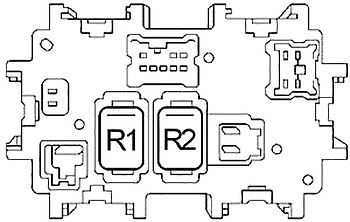
| R1 | Blower | |
| R2 | Accessory | |
Engine compartment fuse box 1
The fuse block is located on the passenger side of the engine compartment.
Diagram 2001-2002
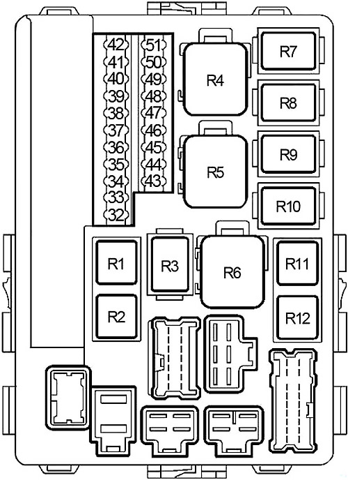
| Number | Amps [A] | Description |
|---|---|---|
| 32 | 15 | Fuel Pump Relay |
| 33 | 10 | IPDM E/R Processor |
| 34 | 10 | Air Conditioning Relay |
| 35 | 20 | Rear window demist relay |
| 36 | 20 | Rear window demist relay |
| 37 | 15 | Throttle control motor relay |
| 38 | 10 | Tail light relay (parking light, license light, tail light) |
| 39 | 20 | Front wiper relay, front wiper motor |
| 40 | 15 | IPDM E/R Processor |
| 41 | 15 | Front fog light relay |
| 42 | 10 | Transmission control module (TCM), speed sensor, turbine speed sensor |
| 43 | – | – |
| 44 | 10 | EVAP absorption volume control solenoid valve, EVAP absorption vent control solenoid valve, vacuum shutoff valve bypass valve, inlet valve timing control solenoid valve, VIAS control solenoid valve |
| 45 | 10 | ABS |
| 46 | 10 | Washing machine motor |
| 47 | 10 | High beam right, daytime running lights |
| 48 | 10 | Left high beam headlight, daytime running lights |
| 49 | 15 | Headlight Low-Left |
| 50 | 15 | Reflector low right |
| 51 | 15 | Engine control module (ECM) relay |
| R1 | Fuel Pump | |
| R2 | Air conditioning | |
| R3 | Ignition | |
| R4 | Cooling fan (№1 (Hello)) | |
| R5 | Cooling fan (№2 (Hello)) | |
| R6 | Cooling Fan (№3 (Lo)) | |
| R7 | Low beam | |
| R8 | High beam headlight | |
| R9 | Front fog light | |
| R10 | Starter | |
| R11 | Throttle control motor | |
| R12 | Motor control module | |
Scheme 2003-2006
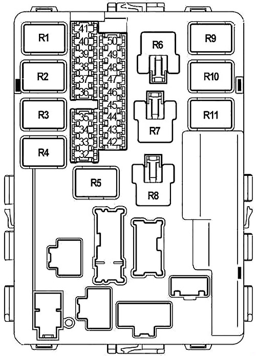
| Number | Amps [A] | Description |
|---|---|---|
| 32 | 20 | Rear window defroster relay |
| 33 | 10 | Air Conditioning Relay |
| 34 | 15 | IPDM E/R Processor |
| 35 | 15 | Engine control module (ECM), ECM relay, NATS antenna amplifier |
| 36 | 15 | Headlight Low-Left |
| 37 | 20 | Rear window demist relay |
| 38 | 10 | Left high beam headlight, daytime running lights |
| 39 | 20 | Front Wiper Relay |
| 40 | 10 | High beam right, daytime running lights |
| 41 | 10 | Tail light relay (parking light, license light, tail light) |
| 42 | 10 | EVAP absorption volume control solenoid valve, EVAP absorption vent control solenoid valve, inlet valve regulation control solenoid valve (VK35DE), VIAS control solenoid valve (VK35DE) |
| 43 | 15 | Front fog light relay |
| 44 | 15 | Throttle control motor relay |
| 45 | 15 | Reflector low right |
| 46 | 15 | Fuel/air ratio sensor, heated oxygen sensor |
| 47 | 10 | Washing machine motor |
| 48 | 10 | A/T PV ignition relay, RPM sensor, turbine RPM sensor |
| 49 | 10 | ABS |
| 50 | 15 | Fuel pump relay |
| R1 | Motor control module | |
| R2 | Highlights | |
| R3 | Low beam | |
| R4 | Starter | |
| R5 | Ignition | |
| R6 | Cooling fan (№1) | |
| R7 | Cooling fan (№3) | |
| R8 | Cooling fan (№2) | |
| R9 | Throttle control motor | |
| R10 | Fuel Pump | |
| R11 | Front fog light | |
Engine compartment fuse box 2
It is near the battery. Remove the fuse box cover by pressing the latch and lifting the cover.
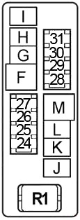
| Number | Amps [A] | Description |
|---|---|---|
| 24 | 10 | 2001-2002: Engine control module, immobilizer control module |
| 25 | 15 | Horn relay |
| 26 | 10 | Generator |
| 27 | – | – |
| 28 | 10 | VQ35DE: electronically controlled front engine mount, electronically controlled rear engine mount |
| 29 | 15 | Seat heating relay |
| 30 | – | – |
| 31 | 15 | Audio |
| F | 50 | Body Control Module (BCM) |
| g | 30 | ABS |
| h | 30 | ABS |
| i | – | – |
| J | – | – |
| K | 40 | Cooling fan relay (№1, 2, 3) |
| L | 40 | Cooling fan relay (№1, 3) |
| m | 40 | Ignition Switch |
| R1 | Horn | |
Fuse Connection Block
Located on the positive terminal of the battery.
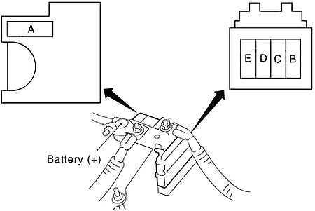
| Number | Amps [A] | Description |
|---|---|---|
| A | 120 | Generator, fuse: “D”, “E”. |
| b | 80 | 2001-2002: Ignition relay (Fuses: “1”, “12”, “13”, “14”, “15”, “32”, “33”, “42”, “44”, “45”, “46”), Fuse: “35”, “40”, “51 |
| 80 | 2003-2006: ignition relay (Fuses: “42”, “46”, “47”, “48”, “49”, “50”), Fuses: “33”, “34”, “35”, “37 “ | |
| C | 60 | 2001-2002: Accessory relay (Fuses: “5”, “6”, “7”), Blower relay (Fuses: “10”, “11”), Fuses: “19”, “20” |
| 60 | 2003-2006: Accessory relay (Fuses: “5”, “6”, “7”), Blower relay (Fuses: “10”, “11”), Fuses: “17”, “19”, “20”, “21” | |
| D | 80 | 2001-2002: High beam relay (Fuses: “47”, “48”), Low beam relay (Fuses: “49”, “50”), Fuses: “34”, “36”, “37”, “38 “, “39”, “41” |
| 80 | 2003-2006: High beam relay (Fuses: “38”, “40”), Low beam relay (Fuses: “36”, “45”), Fuses: “32”, “39”, “41”, “43 “, “44” | |
| E | 100 | 2001-2002: Fuses: ‘D’, ‘F’, ‘G’, ‘H’, ‘L’, ‘K’, ‘M’, ’24’, ’25’, ’26’, ’28’, ’29’ ’31’. |
| 100 | 2003-2006: Fuses: ‘D’, ‘L’, ‘K’, ‘M’, ’28’, ’29’ ’31 |