New Holland TL70, TL80, TL90, TL100 – fuse box diagram
Year of manufacture:
Without cab
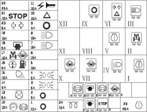
With cab

| No. | Amps [A] | Description |
| 1 | 10 | With Power Shuttle transmission:
Power shuttle circuit, (+ key). |
| 2 | 5 | Without the Power Shuttle:
2-speed circuit; With power shuttle transmission: Power Shuttle, (+ key). |
| 3 | 5 | Position lights front right and rear left |
| 4 | 5 | Left forward and left back lights;
Indicator lights and illumination. |
| 5 | 15 | No booth:
Front work lights with grille; With cab: Lower front work lights. |
| 6 | 15 | With booth:
Rear work lights. |
| 7 | 15 | Long Lights |
| 8 | 15 | Dipped beams |
| 9 | 5 | No cabin with Power Shuttle:
Power Shuttle circuit, (+ battery); With cab: Electronic lifting circuit; With cab and shuttle power transmission: lectronic lifting circuit and Power Shuttle, (+ battery). |
| 10 | 15 | No booth:
Emergency Lights |
| 25 | With booth:
Directions; Emergency lights. |
|
| 11 | 15 | Horn;
Electrical Socket; Buzzer (with Power Shuttle); Lighter (with cab); Rotating warning light (with cab); Overhead lighting (with Power Shuttle cab); Radio (with cab with Power Shuttle); Warning Lamp. |
| 12 | 10 | + instruments;
Seat safety circuit; Trailer brake. |
| 13 | 5 | Engine cut-off solenoids |
| 14 | 5 | With booth:
Electronic lifting circuit, (+ key). |
| 15 | 10 | No booth:
Rear work light; With cab: Rear windows and windshield wipers; Rear window wiper and wiper pump |
| 16 | 5 | Sediment filtration circuit;
A/C compressor circuit (with cabin) |
| 17 | 10 | 4WD Circuit;
Differential lock; Brake light (with cab). |
| 18 | 5 | Rear power take-off circuit |
| 19 | 15 | With booth:
Upper front work lights. |
| 20 | 10 | No booth:
Directions. |
| 5 | With booth:
Digital Instrument Circuitry |
|
| 21 | 10 | Brake lights;
Seat (with cab). |
| 22 | 25 | With booth:
Fan Assembly; Radio. |
| 23 | 5 | Safety start-up circuit |
| 24 | 15 | Thermostart |
| Relay | ||
| I | 70A motor starter relay | |
| II | Electro-hydraulic 4WD. Relay circuit | |
| III | High beam relay | |
| IV | book | |
| V | Beam Relay | |
| VI | With booth:
Relay for side and tail light circuit. No cab: Electronic warning light. |
|
| VII | Differential lock;
Brake light relay circuit. |
|
| VIII | With booth:
Relay for head and head work lights |
|
| IX | 2-speed relay circuit | |
| X | Differential lock relay circuit | |
| XI | With booth:
Front and bottom working light circuit relay. |
|
| XII | With booth:
Rear work light relay circuit. |
|
| A | – | |
| B | With booth:
Conditioner Circuit Relay. |
|
| C | Differential blocking relay circuit | |
| D | Brake light relay circuit | |
| E | Trailer Brake Relay Circuit | |
| F | PTO electro-hydraulic circuit relay | |
| G | PTO electro-hydraulic circuit relay | |
| H | Trailer Brake Relay Circuit | |
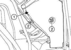
| No. | Amps [A] | Description |
| 1 | 40 | 40A Power Socket. |
| 2 | 40 | Fuses 3, 4, 7, 8, 9, 10, 11 |
| 3 | 50 | Fuses 1, 2, 12, 13, 14, 15, 16, 17, 18, 20, 21, 22, 23, 24;
Starter circuit. |
| 4 | 50 | With booth:
Fuses 5, 6, 19, 25, 26 (working lights) |