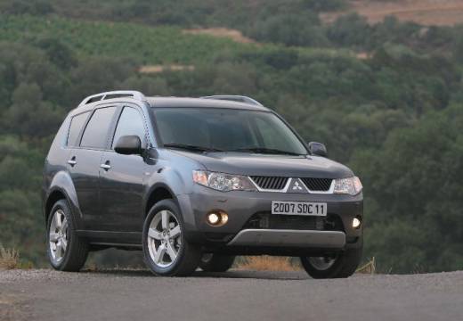
Mitsubishi Outlander – fuse box diagram
Year of manufacture: 2007, 2008, 2009, 2010, 2011, 2012.
Lighter fuse (power socket) in Mitsubishi Outlander Is of fuses 15 and 23 in the fuse box in the passenger compartment.
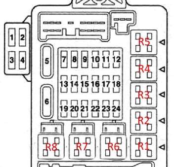
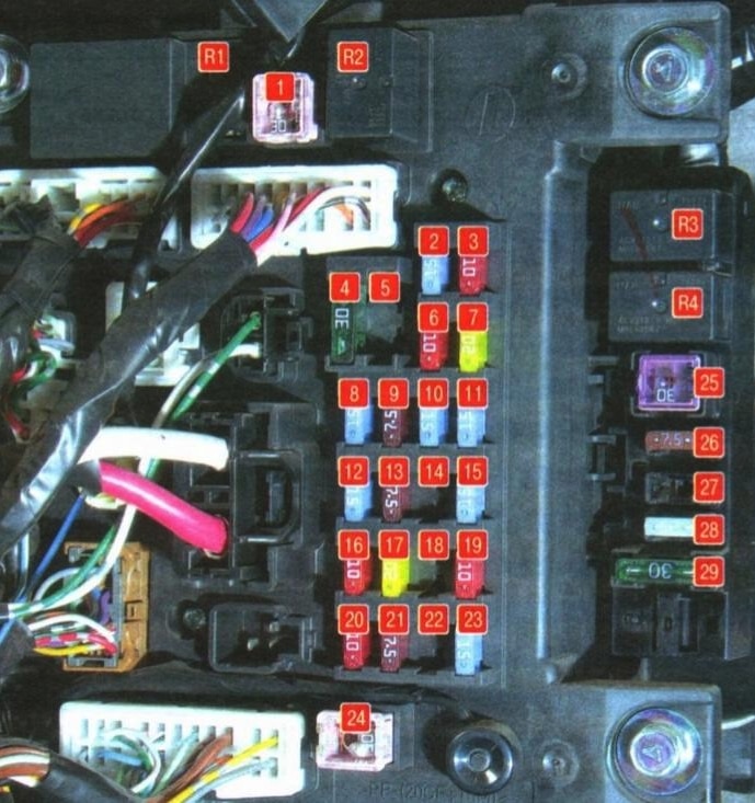
Passenger compartment fuse box
Under the instrument panel on the driver’s side
Description
| 1 | 30A Heater |
| 2 | 15A Stop lamps |
| 3 | 10A Rear fog light |
| 4 | 30A Glass Wiper |
| 5 | Reservation |
| 6 | 10A Auxiliary equipment chain |
| 7 | 20A Door Locks |
| 8 | 15A audio system |
| 9 | 7.5A Auxiliary equipment chain |
| 10 | 15A Interior lamps |
| 11 | 15A Emergency Lights |
| 12 | 15A Rear window washer |
| 13 | 7.5А Control and measuring equipment |
| 14 | Reservation |
| 15 | 15A Cigarette lighter (front power socket) |
| 16 | 10A ignition switch |
| 17 | 20A Electric sunroof |
| 18 | Reservation |
| 19 | 10A Exterior mirrors |
| 20 | 10A four-wheel drive |
| 21 | 7.5A Reversing lights |
| 22 | Reservation |
| 23 | 15A Additional power socket |
| 24 | 30A Electric windows |
| 25 | 30A Heated tailgate window |
| 26 | 7.5А Heated outside mirrors |
| 27 | 15A Power Supply |
| 28 | 20/25A Electric seat |
| 29 | 30A Seat heating |
Retransmission Assignment
- Door Lock Relay
- Heater Relay
- Seat Heater Relay
- Tailgate Window Heater Relay
Fuses and relay boxes in engine compartment
Main box
On the left side of the engine compartment
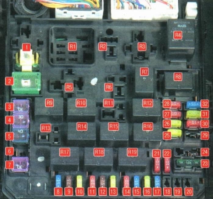
Description
| 1 | 30A Input/Output device |
| 2 | 40A Cooling fan motor |
| 3 | 30A Fan motor capacitor |
| 4 | 30A ABS |
| 5 | 40A ABS |
| 6 | Reservation |
| 7 | 30A Initiator |
| 8 | 15A Front fog lamps |
| 9 | 7.5 Engine management |
| 10 | 20A ACP |
| 11 | 10A buzzer |
| 12 | 7.5A Generator |
| 13 | 20A Headlight washer |
| 14 | 10A Air Conditioning |
| 15 | 15A Accelerator |
| 16 | 20A Burglar Alarm Sound |
| 17 | 15A Heated wiper blades |
| 18 | Reservation |
| 19 | 30A Electric Backdoor |
| 20 | 10A Exterior daylighting system |
| 21 | 10A High beam headlight (left) |
| 22 | 10A Traffic Light (right) |
| 23 | 30A Audio amplifier |
| 24 | 30A Diesel engine electrical equipment |
| 25 | 20A Left passing lamp (with discharge lamps) |
| 26 | 20A Right side passing lamp (with discharge lamps) |
| 27 | 10A Left-Turn Light (with halogen lamps) |
| 28 | 10A Low beam headlight on the right (with halogen lamps) |
| 29 | 10A Motor power supply circuit |
| 30 | 10A Ignition Coil |
| 31 | 20A Motor power supply circuit |
| 32 | 15A fuel pump |
Relay
| R1 | Glow plug relay (for diesel engines) |
| R2 | Radiator Fan Relay |
| R3 | Heater Relay |
| R4 | Motor control relay |
| R5 | Stability Relay |
| R6 | A/C Radiator Fan Relay |
| R7 | Motor control relay |
| R8 | Dipped-beam relay |
| R9 | Motor control relay |
| R10 | Windscreen Heater Relay |
| R11 | Outdoor Daylight Relay |
| R12 | Motor control relay |
| R13 | Anti-theft alarm relay |
| R14 | Automatic transmission relay |
| R15 | Headlight Washer Relay Relay |
| R16 | High beam relay |
| R17 | Front fog light relay |
| R18 | Horn relay |
| R19 | Air conditioning relay |
Relay box
Located next to the main box
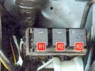
Description
- R1 Slow speed fan relay for the engine cooling system
- R2 Air conditioning fan relay
- Engine cooling system R3 High speed fan relay
Battery box
The positive terminal of the battery contains a high-power fuse box in the form of fuse links.