Mitsubishi Lancer (2007-2018) – fuse box diagram
Year of manufacture: 2007, 2008, 2009, 2010, 2011, 2012, 2013, 2014, 2015, 2016, 2017, 2018.
Lighter fuse (power outlet) in Mitsubishi Lancer Is fuse 13 in the engine compartment fuse box.
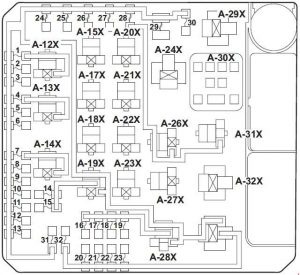
Engine compartment fuse box
| No. | Amps [A] | Description |
| 1 | 15 | Fog light relay. |
| 2 | 7.5 | Motor control module |
| 3 | 20 | Pulley speed sensor < CVT>;
Propeller bridge control module < CVT>;;;. |
| 4 | 10 | Horn and horn relay |
| 5 | 7.5 | Generator |
| 6 | 20 | Headlight Washer |
| 7 | 10 | A/C compressor and A/C compressor clutch relay assembly. |
| 8 | 15 | ETV/oil cooling fan
(SST Twin Clutch); (except vehicles with turbocharger); ETV (vehicles with turbocharger). |
| 9 | 20 | Safety Alarm |
| 10 | 15 | Windshield defroster |
| 11 | – | – |
| 12 | 30 | Power Port |
| 13 | 10 | Daylight relay continuous i
daytime running lights. |
| 14 | 10 | Headlight assembly (top: left) |
| 15 | 10 | Headlight assembly (top: right) |
| 16 | 20 | Headlight (dipping/immersion) (left) |
| 17 | 20 | Headlight (dipped beam and driving beam) (right) |
| 18 | 10 | Headlight assembly (bottom: left) |
| 19 | 10 | Headlight assembly (bottom: right) |
| 20 | 10 | ENG/POWER
(except for vehicles with turbocharger); I/C SPRAY (vehicles with turbocharger). |
| 21 | 10 | Ignition coil 1 to 4 |
| 22 | 20 | Heated oxygen central sensor
in the exhaust pipe; Engine control module; Engine oil control valve; Exhaust gas cleaning solenoid; Evaporative emission ventilation solenoid; Injector 1 to 4; Air flow sensor; Heated oxygen sensor and Vehicle speed sensor <M/T>. |
| 25 | Fuel Line Heater | |
| 23 | 15 | Fuel pump module
(except for vehicles with turbocharger). |
| 20 | Fuel pump module
(vehicles with turbocharger). |
|
| 24 | 30 | Starter |
| 25 | 40 | Valve Lift Control
(except for vehicles with turbocharger). |
| 26 | 40 | ABS Controller |
| 27 | 30 | ABS Controller |
| 28 | 30 | Condenser fan motor;
Condenser fan relay and fan control relay. |
| 29 | 40 | Radiator fan motor i
Radiator Fan Relay |
| 30 | 30 | IOD, fuse #7 to 9 in
passenger compartment. |
| 31 | 30 | Sound amplifier |
| 32 | 30 | Diesel |
| No. |
Relay | |
| A-11X | Light Fog Relay | |
| A-12X | Horn Relay | |
| A-13X | A/C Compressor Clutch Relay | |
| A-14X | – | |
| A-15X | CVT control relay | |
| A-16X | – | |
| A-17X | Headlight Relay (High) | |
| A-18X | Motor control relay
throttle actuator. |
|
| A-19X | – | |
| A-20X | Daylight Continuous Relay | |
| A-21X | Injector Relay | |
| A-22X | – | |
| A-23X | Condenser Fan Relay | |
| A-24X | Control Relay | |
| A-25X | Headlight (Low) Relay | |
| A-26X | Radiator Fan Relay | |
| A-27X | – | |
| A-28X | Fan Control Relay | |
| A-29X | – | |
| A-30X | MFI Relay | |
Fuse box above the battery
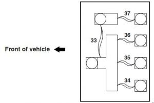
| No. | Amps [A] | Description |
| 33 | 120 | Fuse element no. 37;
Fuse element #34 to 36. |
| 34 | 80 | Fuses nos. 2, 4, 5, 10, 11,12, 14, 15,
17, 18, 20 and 25 in the passenger compartment. |
| 35 | 80 | – |
| 36 | 120 | Fuse 1 to 32 in the engine compartment;
Headlight relay (high); Headlight Relay (Low); MFI Relay. |
| 37 | 80 | Fuse element 1 and 21, 3, 6, 13,
16, 19 and 22 in the passenger compartment and ETACS-ECU (ACC 2 relay and blower relay). |
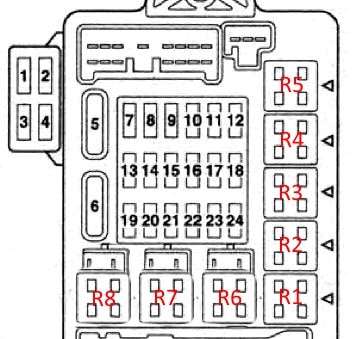
Instrument panel fuse block

| No. | Amps [A] | Description |
| 1 | 30 | Fan motor |
| 2 | 15 | Stop lights (brake lights);
ETACS-ECU; Height-mounted stop light; Rear combination light and gear shift switch assembly. |
| 3 | 10 | Rear fog light |
| 4 | 30 | ETACS-ECU;
Washing machine motor; Windshield wiper motor. |
| 5 | 10 | Data Link Connector |
| 6 | 20 | ETACS-ECU;
Front door lock actuator; Boot lid actuator and switch and rear door lock actuator. |
| 7 | 15 | Audiovisual navigation unit;
CAN box unit; Center panel unit; Hands-free module; Radio; CD player and CD charger; Later Exposure; Satellite radio tuner. |
| 8 | 7.5 | Air conditioning controller;
Column switch; Combination counter; ETACS Controller; Key reminder switch; KOS Controller; Window elevator relay; Wireless control module i Receiver antenna module < vehicles without KOS>. |
| 9 | 15 | Audiovisual navigation unit;
Central unit; Combination counter and key reminder switch. |
| 10 | 15 | ETACS Controller;
Warning spark. |
| 11 | 15 | Rear window wiper |
| 12 | 7.5 | Air conditioning control panel;
Air conditioning control panel; CVT control relay; ABS Controller; center panel unit; column switch; combination counter; heated seat relay; KOS Controller; Rear window demisting relay; Gearshift switch assembly; SRS Controller; Mounting of roof motors; Wireless control module i Receiver antenna module < vehicles with KOS>. |
| 13 | 15 | Accessory socket (front) i cigarette lighter |
| 14 | 10 | Ignition switch circuit |
| 15 | 20 | Mounting of sunroof motors |
| 16 | 10 | Audiovisual navigation unit;
CAN module; Side mirror kit; Radio and CD player or CD changer; Rear display and Remote controlled mirror switch, |
| 17 | 10 | Passenger classification – driver |
| 18 | 7.5 | Audiovisual navigation unit;
Reversing light switch <M/T>; Thruster bridge control module <CVT>; SRS controller; Transmission range switch < CVT>. |
| 19 | 15 | Accessory socket (rear floor console) |
| 20 | 30 | Windshield motor (right);
Main window switch and rear window motor. |
| 21 | 30 | Rear window defogger |
| 22 | 7.5 | Installing side mirrors |
| 23 | 15 | 115 V electrical socket. |
| 24 | 20 25 |
Electric seats |
| 25 | 30 | Heated seat |
| No. | Relay | |
| R1 | Fan motor | |