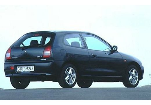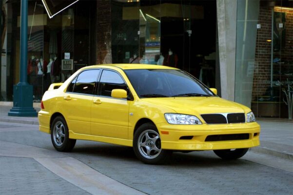
Mitsubishi Lancer (2000-2007) – Fuse box diagram
Year of manufacture: 2000, 2001, 2002, 2003, 2004, 2005, 2006, 2007.
Lighter fuse (socket) in Mitsubishi Lancer (2000-2007) Is fuse 11 in the engine compartment fuse box.
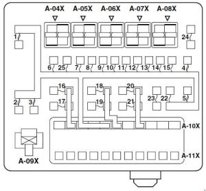
Engine compartment fuse and relay box
| No. | Amp [A] | Description |
| 1 | 60 | Fuse Nos. 15, 16, 19, 20
(in connection block) circuit. |
| 2 | 50 | Fan Controller |
| 3 | 60 | ABS Controller |
| 4 | 40 | Ignition switch circuit |
| 5 | 30 | Main switch for window elevator and
Auxiliary window lift switch. |
| 6 | 15 | Front fog light;
Front fog light indicator light; Front fog light relay and backup connector (for front fog light). |
| 7 | 10 | Horn and Horn |
| 8 | 20 | Air filter air flow sensor;
Camshaft position sensor; Exhaust gas solenoid valve (EGR system); Exhaust gas solenoid valve (purge control system); Engine – A /T – Controller; Motor Controller; Engine control lambda probe; Engine control relay; Engine crank angle sensor; Fan control relay; Fuel injector; Ignition coil relay; Immobilizer controller; Speed control servo Accelerate the idle speed of the body. |
| 9 | 10 | A/C Compressor |
| 10 | 15 | ABS Controller;
Engine-A/T-ECU; Upper stop light and rear combination light. |
| 11 | 15 | Accessory socket |
| 12 | 7.5 | Alternator |
| 13 | 10 | ETACS Controller;
Front indicator lamp; Rear combination lamp; Side and side direction-indicator lamp indicator lamp. |
| 14 | 20 | Solenoid valve assembly
A/T-ECU air conditioning and engine control unit. |
| 15 | 15 | Fuel Pump |
| 16 | 10 | Lighthouse (right) |
| 17 | 10 | Headlight (left) i
High beam indicator lamp. |
| 18 | 10 | Lighthouse (right) |
| 19 | 10 | Lighthouse (left),
Headlight assembly and Headlight leveling switch. |
| 20 | 7.5 | Air conditioning controller;
Luminous Ashtray; Lighter Ashtray Lamp; Combination meter; Fog light switch; Front turn signal indicator; Emergency light switch; Headlight assembly (right); Headlight leveling switch; Heated seat switch; Heated seat controller; License plate lamp; Rear combination lamp; Reostat; Side indicator lamp and Backup connector (for audio). |
| 21 | 7.5 | Combined counter;
Headlight assembly (left); License plate illumination; Position light (left) and Rear combination light (left). |
| 22 | 10 | Combination meter;
Column switch; ETACS controller and front controller. |
| 23 | 10 | Watch;
ETACS controller and Backup connector (for audio). |
| 24 | – | – |
| 25 | 20 | Heated seat assembly and
heated seat switch. |
| 26 | 100 <4G1> 120 <4G6> | Battery;
Topik Nos. 1,2, 3, 4, 5; Fuse Nos. 6, 7, 8, 9, 10, 11, 12, 13, 14, 15, 22 (relay box) and front driver. |
| Relay | ||
| A-04X | Front fog light relay | |
| A-05X | Horn relay | |
| A-06X | – | |
| A-07X | – | |
| A-08X | – | |
| A-09X | Fan Control Relay | |
| A-10X | Front ECU | |
| A-11X | Front ECU | |
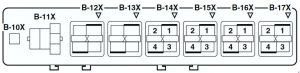
| No. | Relay |
| B-10X | Engine speed detection connector |
| B-11X | – |
| B-12X | – |
| B-13X | – |
| B-14X | Ignition Coil Relay |
| B-15X | A/T Control Relay |
| B-16X | Engine Control Relay |
| B-17X | A/C Compressor Relay |
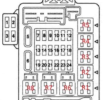
Instrument panel fuse panel
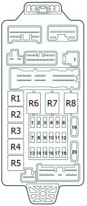
| No. | Amp [A] | Description |
| 1 | 10 | Ignition capacitor and coil |
| 2 | 7.5 | ABS warning light;
Brake warning light; Load warning light; Engine warning light; Column switch; Combination counter; ETACS Controller; Low fuel level warning light, Oil pressure warning light, SRS airbag warning light, SRS Controller; Vehicle speed sensor. |
| 3 | 7.5 | A/T control relay;
Combination counter; Engine-A/T-ECU; ETACS Controller; Input shaft speed sensor; Output shaft speed sensor; Rear combination lamp; SRS-ECU. |
| 4 | – | – |
| 5 | 7.5 | A/C compressor relay;
A/C Controller; Blower Relay; Rear window demisting relay; Front controller; Heated seat relay, Heater control unit; Selection damper control unit outside air/indoor |
| 6 | 7.5 | Remote Controlled Mirror |
| 7 | 20 | Front controller and
Windshield wiper motor. |
| 8 | 7.5 | Motor-A / T-ECU;
Motor Controller; fuel pump relay (1) and Fuel pump relay (2). |
| 9 | 15 | Lighter |
| 10 | – | – |
| 11 | 7.5 | Additional relay socket and
Remote controlled mirror. |
| 12 | 7.5 | ABS Controller |
| 13 | – | – |
| 14 | 15 | ETACS controller and rear wiper motor |
| 15 | 15 | Diagnostic connector |
| 16 | 10 | Rear fog light;
Rear fog indicator light and Rear fog light relay. |
| 17 | – | – |
| 18 | – | – |
| 19 | 30 | Air conditioning controller;
Fan motor; Controller and heating resistor. |
| 20 | 30 | Rear window defogger |
| Relay | ||
| 1 | Fuel pump relay (1) | |
| 2 | Heated seat relay | |
| 3 | Fuel pump relay (2) | |
| 4 | Accessory socket relay | |
| 5 | Rear fog light relay | |
| 6 | Electric Window Relay | |
| 7 | Blower relay | |
| 8 | Rear window demist relay | |