Fuse and relay box diagrams – Mitsubishi Canter 6
Applies to vehicles manufactured over the years:
1993, 1994, 1995, 1996, 1997, 1998, 1999, 2000, 2001, 2002.
Passenger compartment fuse box
Fuse box
Located behind the protective cover on the center panel.

Description
| F1 | 10/15A Left Headlight |
| F2 | 10/15A Headlight Right |
| F3 | 10 / 15A Stop lights, horn, retarder control unit (reset codes) |
| F4 | 10/15A Turning signals |
| F5 | 5A E/dv fuel cut-off |
| F6 | 10A Interior Lighting |
| F7 | 10A Optional equipment |
| F8 | 25/30A Glass elevators, central locking system |
| F9 | 25A air suspension |
| F10 | 15A Automatic transmission control unit (cleaning codes) |
| F11 | 25A Power steering |
| F12 | 25A EZGO System |
| F13 | 15A cigarette lighter |
| F14 | Magnetophone Radio 10A |
| F15 | 10A Optional Equipment |
| F 16 | 10A Mirror unit |
| F17 | 5/10A fuel cut-off relay (24V) |
| F18 | 10/30A input |
| F19 | 10A Reversing lights, exhaust gas recirculation control unit (reset codes) (4D33, 35) |
| F20 | 10A Instrument cluster |
| F21 | 10A Windshield Wiper |
| F22 | 10A Optional equipment |
| F23 | 10A automatic transmission, EZGO system |
| F24 | 10A Automatic transmission |
| F25 | 10A Exhaust gas recirculation system |
| F26 | 10A retarder |
| F27 | 10A exhaust brake |
| F29 | 10А ABS |
| F30 | 10A Automatic Air Conditioning |
| F32 | Air Conditioning 10A |
| F33 | 25/30A Heater Fan |
| F34 | Dimensions 15A |
Separately at the bottom can be: 2 – ASR fuse (10 A), 3 – ammeter fuse (1 A).
Relay box
Installed in the dashboard in front of the passenger seat.
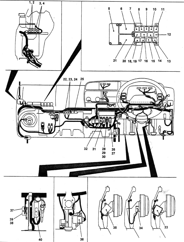


Description
- mirror transmission relay (folding)
- Mirror driving relay (working position)
- Central locking relay (latching)
- central locking relay (unlocking)
- MU-TIC or MULAC Unit
- turn signal switch relay (and turn signal relay – modifications)
- table signal relay (models with exhaust brake)
- thermostatic relay (FE, FF, FG)
- relay size
- high beam relay
- low beam relay
- fan heater relay
- power take-off buzzer
- low speed wiper relay
- parking brake relay
- quick wiper relay
- Mountain brake relay (ABS / ASR)
- Mountain Brake Relay (ABS)
- Intensive Engine Heating Relay System (FB, FD)
- Low engine oil level indicator relay
- LAC Block
- compressor relay (FF)
- Compressor Relay (FF)
- air suspension main relay
- retarder control unit
- Transmission shift relay (FG38)
- Brake light sensor (non-standard)
- Automatic transmission fluid cooler relay (FE)
- Automatic transmission fluid cooler relay (FB)
- EZGO Horn Relay
- fuel cut-off relay
- 4WD mode activation relay
- PPS control unit (FE, FF); mirror drive control unit
- Key lock control unit (models with automatic transmission)
- Instrument cluster control unit (FG38)
- Differential locking control unit (FG38)
- 38, 39 – power take-off clutch relay. 40 – automatic transmission control unit.
Box near the battery
An additional fuse and relay box is located outside the vehicle, next to the battery.


| FH1 | 50A Fuses F1 … 4 |
| FH2 | 50A Fuses F5 … 12 |
| FH3 | 30А ABS |
| FH4 | 30A ABS |
| FH5 | 50A Ignition “B” output |
| FH6 | F31 fuses … 34 |
| FH7 | 100A Generator |
| FH8 | 80A Second generator;
50A Retarder. |

