Mercedes Vito/Viano W639 (2003-2014) – fuse box diagram
Year of manufacture: 2003, 2004, 2005, 2006, 2007, 2008, 2009, 2010, 2011, 2012, 2013, 2014.
Lighter fuse (front) -. Fuse box in engine compartment. Fuse F18/15A
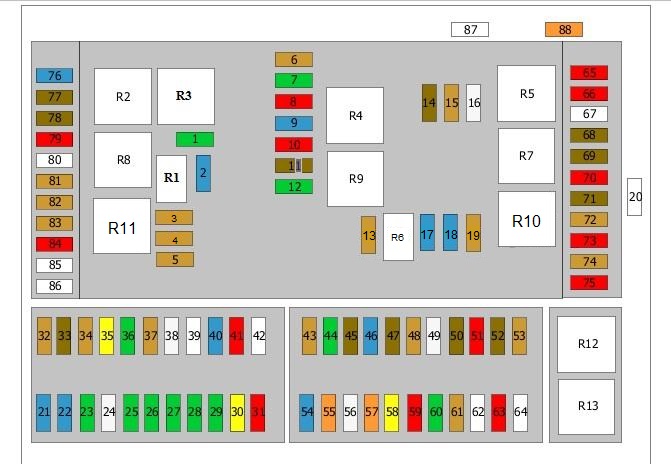
Fuse box in the engine compartment
Location of the fuse box
The fuse box is located on the right side of the engine compartment.
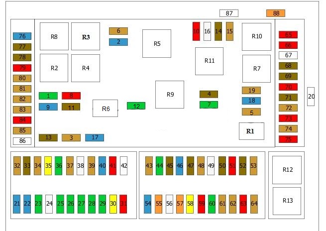
Diagram of the fuse box (VIN – *********** 138470).
| No. | Amps [A] | Description |
|---|---|---|
| 1 | 30A | Front wiper(s) |
| 2 | 15A | Horn |
| 3 | 5A | Change |
| 4 | 7,5A | Heater |
| 5 | 5A | Diagnostic socket;
Switch, exterior lights; Dashboard. |
| 6 | 5A | Engine Management |
| 7 | 30A | Rear Windshield Wiper |
| 8 | 10 A | Power supply;
Motor management. |
| 9 | 15A | Power supply;
Motor management. |
| 10 | 10 A | Power supply;
Motor management. |
| 11 | 7,5A | Terminal 30 |
| 12 | 30A | Heated rear window |
| 13 | 7,5A | Ignition switch;
Instrument panel. |
| 14 | 7,5A | Brake System |
| 15 | 5A | Headlight Leveling |
| 16 | 25A | Starter |
| 17 | 15A | Fuel Pump |
| 18 | 15A | Glove box illumination;
Lighter. |
| 19 | 5A | Radio |
| 20 | 150A | Terminal 30;
On-board Computer. |
| 21 | 15A | 12V Front Socket |
| 22 | 15A | 12V Front Socket |
| 23 | 30A | Trailer Coupling Socket |
| 24 | 25A | Trailer connector socket |
| 25 | 30A | Driver’s seat adjustment |
| 26 | 30A | Passenger Seat Adjustment |
| 27 | 30A | Sliding Door Controller |
| 28 | 30A | Sliding Door Controller |
| 29 | 30A | Rear Fan |
| 30 | 20A | Air Suspension
or 4WD |
| 31 | 10 A | Parking assistance |
| 32 | 5A | Control unit of the tire pressure monitor |
| 33 | 7,5A | Telephone control unit |
| 34 | 5A | TV Tuner |
| 35 | 20A | Heater control unit |
| 36 | 30A | Rear Door Lock |
| 37 | 5A | Rear Air Conditioning |
| 38 | 25A | ABS Control Unit |
| 39 | Not used | |
| 40 | 15A | 12V rear socket |
| 41 | 10 A | Direction indicator control unit |
| 42 | Not used | |
| 43 | 5A | Tachograph |
| 44 | 30A | Heated seats |
| 45 | 7,5A | Phone |
| 46 | 15A | TV Tuner |
| 47 | 7,5A | Front Air Conditioning |
| 48 | 5A | Heater remote control receiver |
| 49 | 25A | Rear sliding roof |
| 50 | 7,5A | Top Console
or sliding roof |
| 51 | 10 A | Interior lights) |
| 52 | 7,5A | TV Tuner |
| 53 | 5A | Outdoor Light Switch |
| 54 | 15A | Navigation control unit |
| 55 | 40A | Brake Vacuum Pump |
| 56 | 25A | Brake System |
| 57 | 40A | Front Fan |
| 58 | 20A | Electric steering wheel lock;
Ignition switch. |
| 59 | 10 A | ATA siren control unit |
| 60 | 30A | Headlight Washers |
| 61 | 5A | Power supply;
Air conditioning. |
| 62 | Not used | |
| 63 | 10 A | Diagnostic connector |
| 64 | Not used | |
| 65 | 10 A | Engine control unit, diesel |
| 66 | 10 A | Engine control unit, diesel |
| 67 | Not used | |
| 68 | 7,5A | TV Tuner |
| 69 | 7,5A | Passenger side mirror |
| 70 | 10 A | Seat adjustment |
| 71 | 7,5A | Overhead console |
| 72 | 5A | Terminal 15 |
| 73 | 10 A | Airbag control unit |
| 74 | 5A | Phone |
| 75 | 10 A | Alarm horn |
| 76 | 15A | Ignition coil;
Terminal 15. |
| 77 | 7,5A | Automatic transmission selector handle |
| 78 | 7,5A | Tachograph |
| 79 | 10 A | Airbag control unit |
| 80 | Not used | |
| 81 | 5A | Trailer Connector |
| 82 | 5A | Shutdown Relay |
| 83 | 5A | Terminal 15 |
| 84 | 10 A | Terminal 87 |
| 85 | Not used | |
| 86 | Not used | |
| 87 | 60A | Air Conditioning Fan |
| 88 | 40A | Secondary Air Injection Pump |
| R1 | Horn relay | |
| R2 | Windshield wiper relay 1 | |
| R3 | Wiper Relay 2 | |
| R4 | Power relay;
Engine management. |
|
| R5 | Startup Relay | |
| R6 | Fuel pump relay | |
| R7 | Terminal 15R Relay | |
| R8 | Terminal 15 relay | |
| R9 | Heated rear window relay | |
| R10 | Not used | |
| R11 | Not used | |
| R12 | Headlight Washer Relay Relay | |
| R13 | Secondary air injection pump relay |
Fuse box diagram (VIN *********** 138471 – ).
| No. | Amps [A] | Description |
|---|---|---|
| 1 | 30A | Front wiper(s) |
| 2 | 15A | Horn |
| 3 | 5A | Change |
| 4 | 7,5A | Heater |
| 5 | 5A | Diagnostic socket;
Switch, exterior lights; Dashboard. |
| 6 | 5A | Engine Management |
| 7 | 30A | Rear Windshield Wiper |
| 8 | 10 A | Power supply;
Motor management. |
| 9 | 15A | Power supply;
Motor management. |
| 10 | 10 A | Power supply;
Motor management. |
| 11 | 7,5A | Terminal 30 |
| 12 | 30A | Heated Rear Window |
| 13 | 7,5A | Ignition switch;
Instrument panel. |
| 14 | 7,5A | Brake System |
| 15 | 5A | Headlight Leveling |
| 16 | 25A | Starter |
| 17 | 15A | Fuel Pump |
| 18 | 15A | Glove box illumination;
Lighter. |
| 19 | 5A | Radio |
| 20 | 225A | Terminal 30;
On-board Computer. |
| 21 | 15A | 12V front socket |
| 22 | 15A | 12V Front Socket |
| 23 | 30A | Trailer connector socket |
| 24 | 25A | Trailer connector socket |
| 25 | 30A | Driver’s seat adjustment |
| 26 | 30A | Passenger Seat Adjustment |
| 27 | 30A | Sliding Door Controller |
| 28 | 30A | Sliding Door Controller |
| 29 | 30A | Rear Fan |
| 30 | 20A | Air Suspension
or 4WD |
| 31 | 10 A | Parking assistance |
| 32 | 5A | Control unit of the tire pressure monitor |
| 33 | 7,5A | Telephone control unit |
| 34 | 5A | TV Tuner |
| 35 | 20A | Heater control unit |
| 36 | 30A | Rear Door Lock |
| 37 | 5A | Rear Air Conditioning |
| 38 | 25A | ABS Control Unit |
| 39 | 5A | Cab package |
| 40 | 15A | 12V Rear Socket |
| 41 | 10 A | Direction indicator control unit |
| 42 | Not used | |
| 43 | 5A | Tachograph |
| 44 | 30A | Heated Seats |
| 45 | 7,5A | Phone |
| 46 | 15A | TV Tuner |
| 47 | 7,5A | Front Air Conditioning |
| 48 | 5A | Heater remote control receiver |
| 49 | 25A | Rear sliding roof |
| 50 | 7,5A | Top Console
or sliding roof |
| 51 | 10 A | Interior lights) |
| 52 | 7,5A | TV Tuner |
| 53 | 5A | Outdoor Light Switch |
| 54 | 15A | Navigation Control Unit |
| 55 | 40A | Brake Vacuum Pump |
| 56 | 25A | Brake System |
| 57 | 40A | Front Fan |
| 58 | 20A | Electric steering wheel lock;
Ignition switch. |
| 59 | 10 A | ATA siren control unit |
| 60 | 30A | Headlight Washers |
| 61 | 5A | Power supply;
Air conditioning. |
| 62 | 5A | Audio port control unit |
| 63 | 10 A | Diagnostic connector |
| 64 | 5A | Central gate control unit |
| 65 | 10 A | Engine control unit, diesel |
| 66 | 10 A | Engine control unit, diesel |
| 67 | Not used | |
| 68 | 7,5A | TV Tuner |
| 69 | 7,5A | Passenger side mirror |
| 70 | 10 A | Seat adjustment |
| 71 | 7,5A | Hanging Console |
| 72 | 5A | Terminal 15 |
| 73 | 10 A | Airbag control unit |
| 74 | 5A | Phone |
| 75 | 10 A | Alarm horn |
| 76 | 15A | Ignition coil;
Terminal 15. |
| 77 | 7,5A | Automatic transmission selector handle |
| 78 | 7,5A | Tachograph |
| 79 | 10 A | Airbag control unit |
| 80 | 5A | Mirrors |
| 81 | 5A | Trailer Connector |
| 82 | 5A | Cut-Off Relay |
| 83 | 5A | Terminal 15 |
| 84 | 10 A | Terminal 87 |
| 85 | 5A | Park/Neutral position switch |
| 86 | Not used | |
| 87 | 60A | Air Conditioning Fan |
| 88 | 40A | Secondary Air Injection Pump |
| R1 | Horn relay | |
| R2 | Windshield wiper relay 1 | |
| R3 | Wiper Relay 2 | |
| R4 | Power relay;
Engine management. |
|
| R5 | Startup Relay | |
| R6 | Fuel Pump Relay | |
| R7 | Terminal 15R Relay | |
| R8 | Terminal 15R Relay | |
| R9 | Heated Rear Window Relay | |
| R10 | Terminal relay 15R | |
| R11 | Terminal relay 15R | |
| R12 | Headlight Washer Relay Relay | |
| R13 | Secondary air injection pump relay |
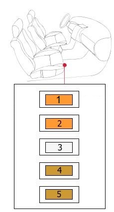
Fuse box 1 in passenger compartment

| No. | Amps [A] | Description |
|---|---|---|
| 1 | 25A | Door Controller (DCM), left side |
| 2 | 25A | Door Controller (DCM), right side |
| 3 | 25A | Control unit with special parameterizable module (PSM) |
| 4 | 25A | Control unit with special parameterizable module (PSM) |
| 5 | 15A | 12V Front Socket |
| 6 | 25A | Charging System |
| 7 | 7,5A | Time Control |
| 8 | 25A | Heater Control |
| 9 | 25A | Opening Ceiling |
| 10 | 80A | Supplementary Restraint System (SRS) |
Fuse box 2 in passenger compartment
| No. | Amps [A] | Description |
|---|---|---|
| 1 | 40A | Supply of fuse boxes;
Additional fuses. |
| 2 | 40A | Supply of fuse boxes;
Additional fuses. |
| 3 | 25A | Second battery charging system |
| 4 | 5A | Charging System |
| 5 | 5A | Temperature sensor |