Mercedes-Benz Vito III W447 (2014-2021) – fuse box diagram
Year of manufacture: 2014, 2015, 2016, 2017, 2018, 2019, 2020, 2021.
Location of the fuse box in the engine compartment
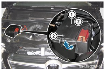
The fuse box is located on the left side in the engine compartment. To open:
- Open the hood.
- Follow the important safety instructions for opening the hood, which are listed in the operating instructions.
- Remove moisture from the fuse box with a dry cloth.
- Open the fastening clamps and remove them from the fuse box.
- Fold the cover up in the direction of the arrow and remove it.
To close:
- Check that the gasket is properly seated on the cover.
- Attach the cover to the back and fold it down.
- Attach the fastening clamps to the fuse box and close it.
- Close the hood.
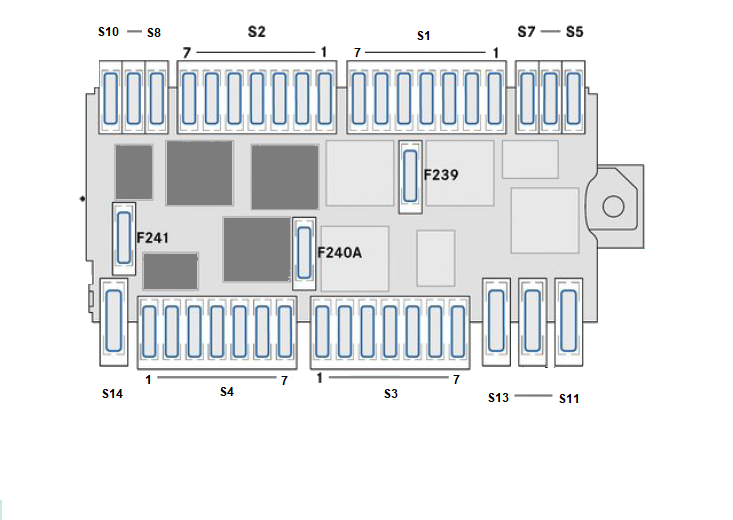
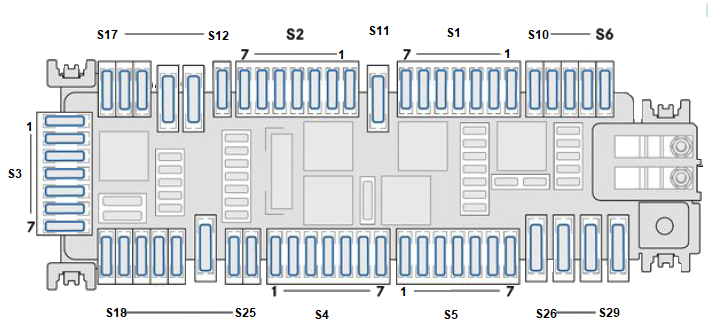
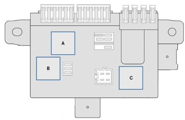
Diagram of the fuse box in the engine compartment
Fuse holder S1
| No. | Description | Fuse | Amps [A] |
|---|---|---|---|
| 1 | ESP Valves | F204 | 25 |
| 2 | Horn | F205 | 15 |
| 3 | Engine control unit | F206 | 5 |
| 4 | Automatic transmission control unit | F207 | 25 |
| 5 | No Assignment | F208 | – |
| 6 | No Assignment | F209 | – |
| 7 | No Attribution | F210 | – |
S2 Fuse Holder
| No. | Description | Fuse | Amps [A] |
|---|---|---|---|
| 1 | No Assignment | F211 | – |
| 2 | Terminal 87 (4) | F212 | 15 |
| 3 | Terminal 87 (2) | F213 | 15 |
| 4 | Terminal 87 (3) | F214 | 10 A |
| 5 | Clamp 87 (1) | F215 | 20 |
| 6 | Motor control unit | F216 | 5 |
| 7 | No Assignment | F217 | – |
S3 Fuse Holder
| No. | Description | Fuse | Amps [A] |
|---|---|---|---|
| 1 | Left lamp range adjustment | F229 | 5 |
| 2 | ESP | F230 | 5 |
| 3 | Adjusting the range of the right headlights | F231 | 5 |
| 4 | No Assignment | F232 | – |
| 5 | Fuel filter heating | F233 | 25 |
| 6 | No Attribution | F234 | – |
| 7 | No Attribution | F235 | – |
S4 Fuse Holder
| No. | Description | Fuse | Amps [A] |
|---|---|---|---|
| 1 | No Attribution | F222 | – |
| 2 | No Attribution | F223 | – |
| 3 | COLLISION AVOIDANCE SUPPORT,
DISTRONIC PLUS |
F224 | 7,5 A |
| 4 | No Attribution | F225 | – |
| 5 | Engine radiator fan / radiator shutter | F226 | 5 |
| 6 | Automatic transmission control unit | F227 | 10 A |
| 7 | Additional oil pump | F228 | 15 |
S5-S14 fuse holder
| No. | Description | Fuse | Amps [A] |
|---|---|---|---|
| S5 | ATA horn (Anti-Theft Alarm) | F201 | 5 |
| S6 | Additional heating control unit | F202 | 20 |
| S7 | HLI LED headlight controller (headlight functions) | F203 | 20 |
| S8 | ESP Control Unit | F218 | 5 |
| S9 | No Assignment | F219 | – |
| S10 | No Assignment | F220 | – |
| S11 | No Attribution | F238 | – |
| S12 | ESP Pump | F237 | 40 |
| S13 | CBC 2 signal acquisition and activation module | F236 | 40 |
| S14 | LED headlight control unit LCU (LED headlight) | F221 | 30 |
Additional tracks on the relay carrier
| No. | Description | Fuse | Amps [A] |
|---|---|---|---|
| – | Windshield Wiper | F239 | 30 |
| – | Starter, terminal 50 | F240A | 25 |
| – | No Attribution | F241 | – |

| No. | Description | Relay |
|---|---|---|
| – | Horn | J |
| – | Windshield wiper, continuous wiping | K |
| – | Windshield wiper on/off switch | L |
| – | Starter | M |
| – | Clamp 87 | N |
| – | No Attribution | O |
| – | No Attribution | P |
| – | No Attribution | Q |
| – | Terminal 15 | R |
| – | No Attribution | S |
| – | No Attribution | T |
Location of the fuse box in the passenger footwell
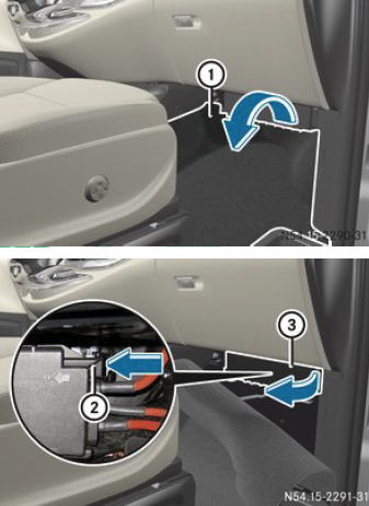 To open:
- To open the passenger door.
- Remove the carpet in the passenger footwell.
- Lift the floor covering in the direction of the arrow.
- Press the retaining clip and lift the cover in the direction of the arrow until it snaps into place.
- Pull the cover forward to remove it from the fuse box.
To close:
- Insert and snap the cover into the holder on the left side of the fuse box.
- Bend the cover until you feel the retaining clip engage.
- Fold the floor covering back.
- Place the floor mat in the passenger footwell.
- Close the passenger door.
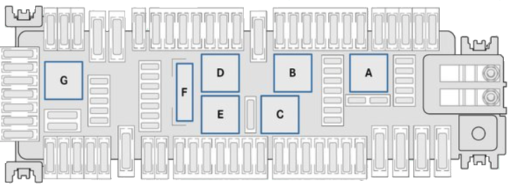
Diagram of the fuse box in the passenger leg room
Fuse holder S1
| No. | Description | Fuse | Amps [A] |
|---|---|---|---|
| 1 | Digital auxiliary air heating timer | F28 | 5 |
| 2 | Radio player;
Radio accessory. |
F29 | 25 A/15 A |
| 3 | Lane assistance, steering wheel | F30 | 10 A |
| 4 | TEMPMATIC heating/air conditioning;
THERMOTRONIC automatic air conditioning |
F31 | 10 A |
| 5 | Control unit in the center console with touch panel | F32 | 7,5 A |
| 6 | Radio (Vito)/Radio (V-Class) | F33 | 5 A/15 A |
| 7 | Lighter | F34 | 15 |
S2 Fuse Holder
| No. | Description | Fuse | Amps [A] |
|---|---|---|---|
| 1 | Driver’s seat control unit | F36 | 7,5 A |
| 2 | Engine compartment fuse box (PDC-E) | F37 | 30 |
| 3 | Airbag control unit | F38 | 7,5 A |
| 4 | DAB/SDARS Digital Radio/TV Tuner | F39 | 5 |
| 5 | No Attribution | F40 | – |
| 6 | No Attribution | F41 | – |
| 7 | Passenger seats control unit | F42 | 7,5 A |
S3 Fuse Holder
| No. | Description | Fuse | Amps [A] |
|---|---|---|---|
| 1 | Casing tube module | F49 | 5 |
| 2 | Radio display and fan | F50 | 7,5 A |
| 3 | Mobile phone support | F51 | 5 |
| 4 | Multimedia Interface | F52 | 5 |
| 5 | Toll System, Japan (DSRC) | F53 | 7,5 A |
| 6 | Air-conditioning fan | F54 | 30 |
| 7 | Ignition lock/electronic steering | F55 | 20 |
S4 Fuse Holder
| No. | Description | Fuse | Amps [A] |
|---|---|---|---|
| 1 | Control unit, front door, left side | F64 | 30 |
| 2 | Control unit, front door, right side | F65 | 30 |
| 3 | Rear wiper, right rear door (Vito) | F66 | 20 |
| 4 | Electric parking brake | F67 | 7,5 A |
| 5 | Airbag control unit | F68 | 7,5 A |
| 6 | Automatic deactivation of the second driver airbag | F69 | 5 |
| 7 | No Attribution | F70 | – |
S5 Fuse Holder
| No. | Description | Fuse | Amps [A] |
|---|---|---|---|
| 1 | No Attribution | F71 | – |
| 2 | 12 V sockets, load compartment | F72 | 15 |
| 3 | Electric parking brake | F73 | 30 |
| 4 | Electric sliding door, left | F74 | 30 |
| 5 | Trailer module 1 | F75 | 15 |
| 6 | Trailer module 2 | F76 | 25 |
| 7 | Trailer module 3 | F77 | 25 |
S6-29 fuse holder
| No. | Description | Fuse | Amps [A] |
|---|---|---|---|
| S6 | No Assignment | F23 | – |
| S7 | Trailer Control Unit | F24 | 7,5 A |
| S8 | Auxiliary battery, charging connector | F25 | 10 A |
| S9 | Trailer Control Unit | F26 | 15 |
| S10 | Fuse box in the passenger footwell in the A-pillar (PDC-F) | F27 | 5 |
| S11 | Rear window heating | F35 | 30 |
| S12 | Rear seat entertainment system | F43 | 10 A |
| S13 | Belt tensioner, front seat, left (PRE SAFE®) | F44 | 40 |
| S14 | Belt tensioner, front seat, right (PRE SAFE®) | F45 | 40 |
| S15 | Exhaust gas aftertreatment, SCR 3 | F46 | 10 A |
| S16 | Exhaust gas aftertreatment, SCR 2 | F47 | 20 |
| S17 | Exhaust gas cleaning, SCR 1 | F48 | 15 |
| S18 | Exhaust aftertreatment, SCR relay | F56 | 15 |
| S19 | Auxiliary Air Heater | F57 | 25 |
| S20 | No Attribution | F58 | – |
| S21 | Passenger seats control unit | F59 | 30 |
| S22 | Driver’s seat control unit | F60 | 30 |
| S23 | Amplifier, sound system | F61 | 40 |
| S24 | Roof turn signals | F62 | 10 A |
| S25 | Fuel supply control unit | F63 | 20 |
| S26 | Panoramic Roof | F78 | 30 |
| S27 | CBC signal acquisition and activation module 1 | F79 | 40 |
| S28 | CBC 3 signal acquisition and activation module | F80 | 40 |
| S29 | Blower, rear compartment air conditioning | F81 | 30 |
Additional tracks on relay carrier

| No. | Description | Fuse | Amps [A] |
|---|---|---|---|
| – | PTC heater charging system | F21 | 200 A |
| – | Auxiliary Battery | F22 | 200 A |
| – | Central Star 2 Door | F82 | 5 |
| – | Ignition lock | F83 | 7,5 A |
| – | Center console control/control unit on the left, next to the steering wheel | F84 | 7,5 A |
| – | Receiver/Remote Control Module | F85 | 5 |
| – | RF Antenna | F86 | 5 |
| – | Diagnostic Link | F87 | 10 A |
| – | Instrument cluster | F88 | 10 A |
| – | Light Switch | F89 | 5 |
| – | Blind Spot Wizard | F90 | 5 |
| – | Exhaust aftertreatment, SCR control unit | F91 | 5 |
| – | Fuel supply control unit | F92 | 5 |
| – | Radio Accessories | F93 | 7,5 A |
| – | Toll system, Japan (DSRC) | F93 | 7,5 A |
| – | Unattributed | F94 | – |
| – | Clipboard Lighting | F95 | 5 |
| – | Rear windshield wiper, rear door/rear screwdriver, left (Vito) | F96 | 15 |
| – | PARKTRONIC/active parking assistant | F97 | 5 |
| – | CBC control line signal acquisition and actuator module | F98 | 5 |
| – | Tire Pressure Monitor | F99 | 5 |
| – | Amplifier, sound system | F100 | 5 |
| – | Hanging Control Panel | F101 | 10 A |
| – | Unattributed | F102 | – |
| – | Basic wiring, cab, taximeter | F103 | 5 |
| – | Rear entertainment, display, left side | F104 | 5 |
| – | Rear entertainment, display, right | F105 | 5 |
| – | Camera for Driver Assistance Systems | F106 | 5 |
| – | Basic cabling for TV/movement surveillance cameras | F107 | 5 |
| – | Reversing Camera/360° Camera | F108 | 7,5 A |
| – | No Assignment | F109 | – |
| – | CBC 5 signal acquisition and actuator module | F110 | 30 |
Relay Diagram
| No. | Description | Relay |
|---|---|---|
| – | Terminal 15 relay | A |
| – | Rear window wiper | b |
| – | Terminal 15 R2 | C |
| – | Rear Window Heater | D |
| – | Terminal 15 R1 | mi |
| – | Clamp 30G | F |
| – | Exhaust gas treatment;
SCR feed pump. |
g |
Fuse box in place of A-pillar in passenger leg room
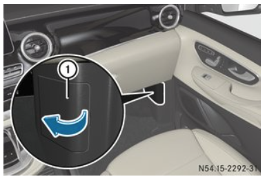
To open:
- Open the passenger door.
- Unfold the cover in the direction of the arrow and remove.
- You will see the fuse box on the A-pillar.
To close:
- Insert the cover into the side cover panel on the left side and press it down.
- Close the passenger door.
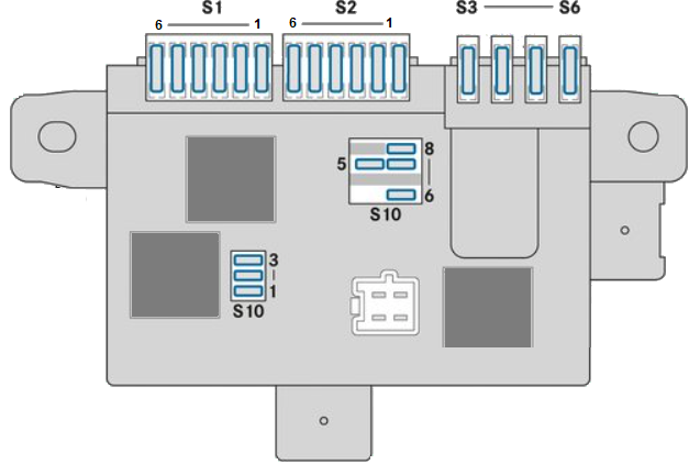
Fuse box in the A-pillar diagram in the passenger leg room
Fuse holder S1
| No. | Description | Fuse | Amps [A] |
|---|---|---|---|
| 1 | Rear seat heating/ventilation, row 1 left | F305 | 10 A |
| 2 | Rear seat heating/ventilation, row 1 right | F308 | 10 A |
| 3 | Rear seat heating/ventilation, row 2 left | F310 | 10 A |
| 4 | Rear seat heating/ventilation, row 2 right | F309 | 10 A |
| 5 | No Attribution | F316 | – |
| 6 | Rear seat heating/ventilation control unit | F317 | 5 |
S2 Fuse Holder
| No. | Description | Fuse | Amps [A] |
|---|---|---|---|
| 1 | Special Programmable Module (PSM) | F303 | 25 |
| 2 | Special Programmable Module (PSM) | F304 | 25 |
| 3 | Refrigerator in the center console | F306 | 10 A |
| 4 | Voltage Transformer | F312 | 30 |
| 5 | Electric sliding door on the right/rear door EASY-PACK | F311 | 30 |
| 6 | No Assignment | F318 | – |
S3-6 fuse holder
| No. | Description | Fuse | Amps [A] |
|---|---|---|---|
| S3 | Marco Polo Charger, Charging Connector | F300 | 25 |
| S4 | Terminal 30 body/cupholder manufacturer, center console | F321 | 25 A/10 A |
| S5 | Unattributed | F302 | – |
| S6 | Auxiliary Air Heater | F323 | 25 |
S10 Fuse Holder
| No. | Description | Fuse | Amps [A] |
|---|---|---|---|
| 1 | Tachograph | F301 | 5 |
| 2 | No Assignment | F307 | – |
| 3 | Tachograph | F315 | 7,5 A |
| 5 | If the key is in position 2 in the ignition: signal to turn on the refrigerator, cup holder, voltage divider in the center console | F314 | 5 |
| 6 | Clamp 61 Only bodybuilder/Westfalia bodybuilder | F319 | 15 A/5 A |
| 7 | Clamp 15 Westfalia bodybuilder/equipment/bodybuilder only | F320 | 15 A/5 A |
| 8 | Auxiliary hot air heater timer | F322 | 5 |
Relay Diagram
| No. | Description | Relay |
|---|---|---|
| – | Terminal 15 relay | A |
| – | No Attribution | b |
| – | No Attribution | C |
Fuse box in the rear compartment

To open: o
- To open the tailgate.
- Remove the tool kit from the storage compartment in the rear (see vehicle owner’s manual).
- Remove the tool holder from the side panel of the shell.
- You will see the three fuse holders and the relay holder.
To close:
- Insert and snap the tool holder into the storage compartment on the back.
- Stow tools and equipment and insert and lock the glove box lid (see vehicle owner’s manual).
- Close the tailgate.
Rear compartment fuse and relay box diagram

Fuse holder and relay holder behind the tool holder.
| No. | Description | Fuse | Amps [A] |
|---|---|---|---|
| 1 | 12 V socket, first row of seats, left-hand side | F352 | 15 |
| 2 | 12 V socket, second row of seats, left-hand side | F350 | 15 |
| 3 | 12 V socket, second row of seats, right | F351 | 15 |
| No. | Description | Relay |
|---|---|---|
| 4 | 12 V sockets in rear compartment | K127 |
Pre-fuse box location
 Open battery tray at the base of the right front seat The pre-fuse box is located next to the starter battery at the base of the right front seat. Always have the fuses in the fuse box replaced by a qualified specialist workshop.
Diagram of the pre-fuse box
 Fuses A3, A7, A10, A11, A13, and A16 are located at the rear.
| No. | Description | Fuse | Amps [A] |
|---|---|---|---|
| 1 | No Attribution | A16 | – |
| 2 | No Attribution | A15 | – |
| 3 | Starter | A1 | Pyrofuse |
| 4 | Fuse box in the passenger footwell in the A-pillar (PDC-F) | A8 | 150 A |
| 5 | Additional Battery | A12 | 150 A |
| 6 | Control unit, preheating system | A2 | 100 A |
| 7 | Alternator | E2 | 350 A |
| 8 | Engine radiator fan | A10 | 100 A |
| 9 | No Attribution | A9 | – |
| 10 | Engine compartment fuse box (PDC-E) | A7 | 150 A |
| 11 | No Assignment | A14 | – |
| 12 | No Assignment | A3 | – |
| 13 | Fuse box in passenger footwell (PDC-P) | A6 | 250 A |
| 14 | CBC signal acquisition and activation module | A13 | 40 |
| 15 | No Assignment | A5 | – |
| 16 | Electrical Control | A11 | 100 A |
| 17 | Rear compartment sockets | A4 | 50 A |