Mercedes-Benz CLS W219 (2004-2010) – fuse box diagram
Year of manufacture: 2004, 2005, 2006, 2007, 2008, 2009, 2010.
Lighter fuse (electrical outlet) in the Mercedes CLS W219 (2004-2010). is fuse 47 in the fuse box
Fuse box in the trunk
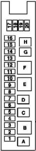
| Number | [A] | Description |
| 1 | 30 | Change Partial adjustment of the front passenger seat Partial electrical adjustment switch for the driver’s seat (from 2007 onwards). Front driver’s side seat adjustment control with memory |
| 2 | 30 | Change Driver’s seat partial electric adjustment Partial electric adjustment switch for the passenger seat (from 2007 onwards). Passenger-side front seat adjustment control unit with memory |
| 3 | 7,5 | TPM [RDK] (Tire Pressure Monitor) Control Unit PTS control unit (Parktronic) Navigation processor Combined TV tuner (analog / digital) |
| 4 | 20 | With the exception of the 156,983 engine (CLS 55 AMG) and the 272,985 engine: The fuel pump is protected by a fuel pump relay |
| 7,5 | Applies to the 113,990 engine (CLS 55 AMG): The charge air cooler circulation pump is protected by the charge air cooler circulation pump relay | |
| 5 | – | Reserve courier 2 |
| 6 | 40 | Audio gateway control unit |
| 7 | 15 | Rear wiper relay |
| 8 | 7,5 | Left antenna amplifier module Alarm horn alarm horn signal with additional battery ATA [EDW] tilt sensor |
| 9 | 25 | Overhead control panel control unit |
| 10 | 40 | Heated rear window |
| 11 | 20 | – |
| 12 | 15 | American version: starter socket |
| 13 | 15 | Internal Socket |
| 14 | – | – |
| 15 | 10 | CL fuel filling motor [ZV] |
| 16 | 20 | HS [SIH] and seat ventilation control unit |
| 17 | 20 | – |
| 18 | 20 | – |
| 19 | 20 | Pneumatic multicontour pump with seat |
| 20 | 7,5 | Rear window blind relay |
| Relay | ||
| ZA | Fuel Pump Relay (except 113,990 (CLS 55 AMG), 156,983 (CLS 63 AMG), 272,985)
Charge air cooler circulation pump relay (113,990 (CLS 55 AMG)) |
|
| W | Relay 2, terminal 15R | |
| to | Reserve courier 2 | |
| re | Reservation | |
| mi | Heated rear window relay | |
| fa | Relay 1, terminal 15R | |
| sun | Fuel tank cover polarity change relay 1 | |
| H. | Fuel tank cover polarity change relay 2 | |
Instrument panel fuse panel

| Number | [A] | Description |
| 21 | 30 | Right tailgate control unit |
| 22 | 30 | Front right door control unit |
| 23 | 30 | Passenger-side front seat adjustment control unit with memory |
| 24 | 25 | Rear Module Keyless Go Control Unit Left rear door Keyless Go control unit Right rear door Keyless Go control unit |
| 25 | 20 | Stationary heater (STH) |
| 5 | Additionally protected by a polyswitch fuse for the stationary heater: STH radio remote control receiver |
|
| 26 | 7,5 | CD changer |
| 27 | – | Reservation |
| 28 | 15 | Radio |
| 5 | Radio control panel and navigation unit Unit Operation, display and control unit |
|
| 29 | 7,5 | Steering column module Rotating Light Switch Controller SIA [EZS] |
| 30 | 7,5 | Data Link Connector |
| 31 | 5 | Upper control panel Intermittent load cut-off relay (until 2007). |
| 32 | 30 | Left rear door control unit |
| 33 | 30 | Front left door control unit |
| 34 | 30 | Control unit for front driver’s seat adjustment, with memory |
| 35 | 5 | WSS (Weight Sensing System) control unit |
| 36 | 25 | HS [SIH] and seat ventilation control unit Right SAM control unit |
| 37 | 15 | AIRmatic with ADS control unit |
| 38 | 7,5 | NECK-PRO Headrest Relay |
| 39 | 5 | Lower control panel |
| 40 | 10 | HS [SIH] and seat ventilation control unit |
| 41 | 5 | Central gate control unit |
| 42 | 7,5 | ME-SFI control unit [ME] Unit Driver-side SAM control unit with fuse and relay module |
Fuse box in engine compartment

| Number | [A] | Description |
| 43 | 15 | Applies to M156, M272, M273:
ME-SFI control unit [ME] Rear SAM control unit with fuse and relay module CDI control unit ME-SFI [ME ] control unit |
| 44 | 15 | Valid for M642: CDI control unit |
| 45 | 7,5 | AIRmatic with ADS control unit |
| 46 | 7,5 | 5-speed automatic transmission (NAG): ETC control unit [EGS] 7-speed automatic transmission: Electric control unit (VGS) |
| 47 | 5 | ESP Control Unit |
| 48 | 7,5 | Control unit for restraint systems |
| 49 | 7,5 | Left front reversible emergency voltage retractor (from 2007 onwards). Emergency voltage reversing retractor front right (from 2007) Safety systems control unit (until 2007) Occupied front passenger seat and child seat recognition sensor (until 2007). NECK-PRO headrest relay (2006) |
| 50 | 5 | VICS power separation point |
| 51 | 5 | – |
| 52 | 7,5 | Glovebox illumination with switch Instrument cluster Rotary switch lights Headlight Bi-xenon: Headlight Range Control Unit |
| 53a | 15 | Horn relay |
| 53b | 15 | Horn relay |
| 54a | 15 | Illuminated cigar lighter |
| 54b | 15 | Illuminated cigar lighter |
| 55 | 7,5 | ICS power separation point |
| 56 | 40 | Windshield wiper motor |
| 57 | 25 | Applies to M156, M272, M273:
ME-SFI control unit [ME] Rear SAM control unit with fuse and relay module CDI control unit |
| 58 | 15 | Blowdown Control Valve (up to 2007) Applies to the 272 engine: AAC with integrated control of an additional fan motor (until 2007). US version: Activated carbon tank shut-off valve (until 2007). O2 sensor right downstream of TWC [KAT] |
| 59 | 15 | Startup Relay |
| 60 | 10 | Valid for engine 113,990 (CLS 55 AMG), 156,983 (CLS 63 AMG): Oil cooling fan |
| 61 | 40 | Electric Air Pump |
| 62 | 30 | Reservation courier |
| 63 | 15 | – |
| 64 | 7,5 | Rotating light switch panel Control and operation of the automatic climate control Comfort Instrument cluster (until 2007) AAC control and operation unit [KLA] (until 2007) |
| 65 | 20 | CIS Controller [EZS] Controller electric steering lock |
| 66 | 7,5 | Valid for left-hand drive vehicles: Right front light assembly Valid for right hand drive vehicles: Front left light assembly bi-xenon headlight: HRA power module |
| 67 | 10 | Stop light switch |
| Relay |
||
| I | Relay 87, engine |
|
| K | Terminal 87 relay, chassis | |
| L | Startup Relay | |
| M | Reservation courier | |
| N | Terminal 15 relay | |
| O | Horn relay | |
| P | Terminal 15R Relay | |
| R | Air pump relay (except 113.990 (CLS 55 AMG) and engine 156.983 (CLS 63 AMG)) Oil cooling fan relay (engine 113.990 (CLS 55 AMG) and 156.983 (CLS 63 AMG) only) |
|
| S | AIRmatic Relay (semi-active air suspension) | |
Front pre-fuse box
Front

Behind
| Number | [A] | Description |
| 68 | 200 | PTC heating amplifier (starting 1.6.06) |
| 69 | 150 | – |
| 70 | 150 | Additional battery relay (until 31.5.06) |
| 71 | 150 | AAC with integrated additional fan motor control |
| 72 | 50 | Hydraulic unit SBC (until 31.5.06) ESP control unit (from 1.6.06) |
| 73 | 40 | Hydraulic unit SBC (until 31.5.06) ESP control unit (from 1.6.06) |
| 74 | 40 | AIRmatic Relay |
| 75 | 40 | Right SAM control unit |
| 76 | 40 | Right front reversible emergency voltage retractor (from 1.6.06) |
| 77 | 40 | Heating system recirculation unit |
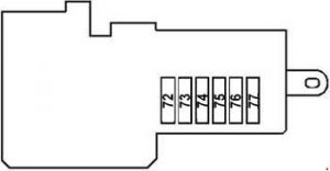
Rear inlet box
Front

Rear

| Number | [A] | Description |
| 78 | 200 | Driver-side SAM control unit with fuse and relay module |
| 79 | 200 | Rear SAM control unit with fuse and relay module |
| 80 | 150 | SAMcontrol controller with fuse and relay module |
| 81 | 150 | Internal fuse box |
| 82 | 150 | AMG Vehicles:
FP Fuse (F82A) |
| F82A | 30 | Left Controller Fuel Pump Controller Right |
| F83B | 40 | Air injection relay |
| 83 | 30 | – |
| 84 | 5 | Battery sensor (2007 and later) Battery Control Unit (up to 2007) |
| 85 | 5 | Voice Control System (VCS) [SBS]) Control unit Portable Universal CTEL Interface (UPCI [UHI]) Control Unit Japanese version: GPS receiver control unit US version: CTEL Compensator [TEL], data compensator |
| 86 | 5 | American version: SDAR control unit (until 2007). |
| 87 | 30 | Pneumatic pump for dynamic seat control |
| 88 | 30 | TLC control unit [HDS] |
| 89 | 40 | – |
| 90 | 40 | Left front reversible emergency voltage retractor (from 2007 onwards). |
| 91 | 30 | Valid with engine 272,985: Fuel pump control unit (from 2007 onwards). |