Mercedes A-Class w169 (2004-2012) – Fuse box diagram
Year of manufacture: 2004, 2005, 2006, 2007, 2008, 2009, 2010, 2011, 2012.
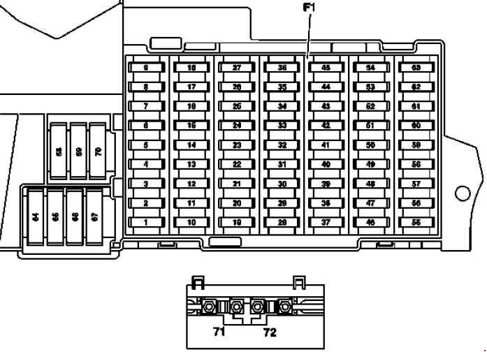
Lighter fuse (electrical outlet) in Mercedes A-Class w169 (2004-2012). Is fuse 53 in the fuse box
Fuse box in the passenger footwell
The fuse box is located in the passenger leg room in front of the seat.
| No. |
Description |
Amps [A] |
| 1 | Stop light switch | 10 |
| Valid for code (U62)
Package Lights and Sight: Stop light switch. |
5 | |
| 2 | Heated rear window | 25 |
| 3 | CIS instrument cluster control unit [EZS] | 7.5 |
| 4 | CIS Controller [EZS];
Electric steering wheel lock command. |
15 |
| 5 | Valid without code (580) Automatic air conditioning and without code (581)
Automatic comfort air conditioner: Heating control and operating unit; Valid for code (580) Automatic air conditioning: AAC control unit [KLA]; Valid for code (581) comfort automatic air conditioning: AAC comfort control unit [KLA]. |
7.5 |
| 6 | Left horn;
Right horn. |
15 |
| 7 | Fuel Pump Relay | 25 |
| Valid for model 169.090:
DC/DC converter control unit |
5 | |
| 8 | Hanging control panel control unit | 25 |
| 9 | ESP and BAS control unit | 40 |
| 10 | Fan controller connector/internal wiring | 40 |
| 11 | Valid for engine 266:
87 relay circuit, motor |
30 |
| Valid for the 640 engine:
87 relay circuit, motor |
40 | |
| 12 | Steering column module;
Multi-function steering wheel. |
5 |
| 13 | Front left door control unit | 25 |
| 14 | Front right door control unit | 25 |
| 15 | ESP and BAS control unit | 25 |
| 16 | Data link connector;
PTS control unit. |
10 |
| 17 | Rotating Light Switch | 5 |
| 18 | Refers to 711, 716 gearboxes:
Backup light switch; Applies to model 169.090: Controller sBKGN air conditioning compressors; Energy monitoring control unit; Vacuum pump control unit 1; Vacuum pump control unit 2. |
7.5 |
| 19 | Micromechanical Speed Sensor AY | 5 |
| 20 | Control unit for restraint systems | 7.5 |
| 21 | Startup Relay | 30 |
| 22 | Instrument cluster | 7.5 |
| 23 | Washing machine nozzle heating | 7.5 |
| Valid for engine 640 as of 1.9.08:
Fuel filter condensation sensor with heating element. |
20 | |
| 24 | Electric power steering control unit (ES) | 7.5 |
| 25 | Stop light switch;
ESP and BAS control unit. |
7.5 |
| 26 | You are referring to the 722 gearbox:
Electronic control unit for the shift lever module. |
7.5 |
| 27 | Valid for 722 gearbox:
CVT (continuously variable automatic transmission) control unit. |
10 |
| 28 | Rotating Light Switch | 5 |
| 29 | SAM control unit | 30 |
| 30 | 87F relay circuit | 25 |
| 31 | Central gate controller (vehicles until 30.11.05);
Rotating light switch; Automatic light switch; Daylight sensor; Rain and light sensor. |
5 |
| 32 | Valid for engine 266:
ME-SFI control unit [ME]; Valid for 169.090: Energy monitoring control unit. |
7.5 |
| 33 | Radio;
Radio and navigation unit; COMAND (Japan) operation, display and control unit. |
15 |
| 34 | Left rear door control unit | 25 |
| 35 | Right tailgate control unit | 25 |
| 36 | Cell phone separation point;
Trailer control unit. |
7.5 |
| Trailer control unit;
PTS control unit. |
10 | |
| 37 | Security Systems Control Unit
Front passenger seat occupancy recognition sensor; Front passenger seat and child seat occupancy recognition sensor |
7.5 |
| 38 | Front cigarette lighter with ashtray lighting | 25 |
| 39 | Windshield wiper motor | 25 |
| 40 | Overhead control panel control unit | 7.5 |
| Roof Engine | 25 | |
| 41 | Liftgate wiper motor | 15 |
| 42 | Glove box lighting with switch;
Left and right cosmetic mirror illumination; Footwell lighting switch (driving school package); Foot operation monitor switch (driving school package); VICS + ETC supply voltage separation point (Japan). |
7.5 |
| 43 | Valid for engine 266:
87M1 e-clamp connector sleeve. |
15 |
| Valid for the 640 engine:
87M1e terminal connector bushing. |
7.5 | |
| Valid for 169.090:
Vacuum pump control unit 1, |
20 | |
| 44 | Valid for engine 266:
87M2e terminal connector bushing, |
15 |
| Valid for the 640 engine:
87M2e terminal connector bushing. |
20 | |
| 45 | Valid for the 640 engine:
CDI control unit; Valid for model 169.090: vacuum pump control unit 2. |
25 |
| 46 | Telephone control unit, (Japan);
E-net Compensator; Portable Universal CTeL Interface (UPCI [UHI]) control unit. |
7.5 |
| Bass Module Speaker (Japan) | 25 | |
| Amplifier for public address | 40 | |
| Valid for model 169.090:
Charging control unit. |
5 | |
| 47 | Telephone exchange, (Japan);
Universal Portable CTEL Interface (UPCI [UHI]); Control unit Cell phone separation point; Voice Control System (VCS [SBS]); Control unit; Applies to model 169.090: Charger 1. |
7.5 |
| 48 | ATA [EDW] / trailer protection / interior protection control unit;
Alarm signal with additional battery; Valid for model 169.090: loader 2. |
7.5 |
| 49 | Upper control panel;
Heated front seat cushion on the left; Left heated front seat cushion; Heated element on the right front seat; Right front seat warmer in the back. |
25 |
| 50 | CD Switch;
Multimedia interface control unit; Digital TV tuner; Digital audio broadcast control unit; VICS + ETC Supply voltage separation point (Japan). |
7.5 |
| Applies to government vehicles:
Roof light bar; Circuit connector sleeve 30. |
30 | |
| 51 | Valid for 169.090:
Cooling Fan; Low temperature cooling pump. |
10 |
| 52 | VICS + ETC (Japan) voltage separation point (vehicles until 31.5.06);
Valid for model 169.090: Electric drive control unit. |
5 |
| Spare parts (vehicles from 1.6.06) | 7.5 | |
| Emergency call system control unit (USA) (vehicles to 31.5.06) | 7.5 | |
| 53 | Rear cigar lighter with ashtray
Interior socket. |
30 |
| 54 | Amplifier for sound system;
Bass module speaker. |
25 |
| Valid for 169.090:
Electric drive control unit. |
5 | |
| 55 | Front left headlight (bi-xenon);
Right front headlight (bi-xenon). |
7.5 |
| Front left light assembly (Hi-Xenon) | 10 | |
| 56 | Reservation | 10 |
| Right Front Light Assembly (Hi-Xenon) | 10 | |
| 57 | Trailer hitch socket (13-pin) (vehicles from 1.6.05) | 15 |
| Audio port control unit (Japan) (vehicles to 31.5.05) | 25 | |
| SDAR control unit;
Emergency call system control unit (USA). |
7.5 | |
| 58 | Trailer control unit;
Valid for model 169.090: Vehicle door control unit. |
25 |
| 59 | Trailer control unit (vehicles up to 31.5.05)
Trailer hitch socket (13-pin) (vehicles from 1.6.05 onwards). |
20 |
| Valid for 169.090:
Battery management system control unit 1. |
5 | |
| 60 | Driver’s seat connector block | 20 |
| 61 | Front passenger seat connection block | 20 |
| 62 | Relay circuit 15 (2) (SA: xenon, cell phone) | 25 |
| 63 | Spare parts (vehicles up to 31.5.05) | – |
| Audio control unit (Japan) (vehicles from 1.6.05);
Applies to Government vehicles: Lightbar on the roof. |
25 | |
| Control unit for the emergency call system (USA) (vehicles from 1.6.05);
SDAR control unit. |
7.5 | |
| Valid for 169.090:
Battery management system control unit 2. |
5 | |
| 64 | Valid for engine 266:
Air pump relay. |
40 |
| Valid for the 640 engine:
Engine wiring harness / engine compartment connector; Light output phase. |
80 | |
| 65 | Electric power steering control unit (ES) | 80 |
| 66 | SAM control unit | 60 |
| 67 | Circuit 15R relay (2) (SE) | 50 |
| 68 | Valid for engine 266.920 and engine 266.940 with 722 gearbox:
AAC with integrated control of additional fan motor. |
50 |
| Valid for 640.940, 640.941, 266.960, 266.980 engines and for 266.920, 266.940 engines with (Tow Hitch):
AAC with integrated additional fan motor control. |
60 | |
| 69 | Circuit 15R relay (1) | 50 |
| 70 | Circuit 15 relay (1) | 60 |
| 71 | Valid for the 640 engine:
PTC heater booster. |
150 |
| 72 | Circuit 30 connector sleeve
Special multifunction vehicle control unit (SVMCU [MSS]) (Taxi). |
60 |
| No. |
Description |
Amps [A] |
| 80 | Reserved for special purpose vehicles | 30 |
| 81 | Reserved for special purpose vehicles | 30 |
| 82 | Reserved for special purpose vehicles | 30 |
| 83 | Reserved for special purpose vehicles | 30 |
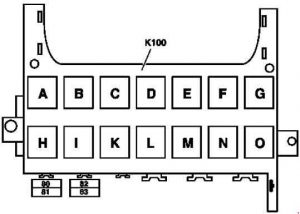
| Relay | ||
| A | Circuit 15R relay (2) (SA) | |
| B | Circuit 15R relay (1) | |
| C | Fanfare horn relay relays | |
| D | Heated rear window relay | |
| E | Wiper Relay Stage 1/2 | |
| F | Wiper On/Off Switch Relay | |
| G | Circuit 15 relay (1) | |
| H | Reservation courier | |
| I | Air Pump Relay | |
| K | Fuel Pump Relay | |
| L | Motor Circuit 87 Relay | |
| M | Starter Relay | |
| N | Relay circuit 87F | |
| O | Relay circuit 15 (2) (SA: xenon, cell phone) | |