Kubota M9540 – fuse box diagram
Fuse box

| Number | Amps [A] | Description |
| 1 | 5 | Startup Relay |
| 2 | 15 | Auxiliary seat with air suspension/air suspension (if equipped) |
| 3 | 15 | Work Light (front, side) |
| 4 | 10 | Air Conditioning (compressor) |
| 5 | 30 | Air conditioner (motor fan) |
| 6 | 15 | Lighter |
| 7 | 15 | Work Light (front) |
| 8 | 15 | Work Light (Rear) |
| 9 | 20 | Backup fuse |
| 10 | 20 | Flickering (danger) |
| 11 | 20 | Headlight, Tail light |
| 12 | 10 | Counter;
Radio (backup); Horn. |
| 13 | 10 | Direction indicator;
Stop lamp. |
| 14 | 5 | Counter panel;
OPC. |
| 15 | 5 | Alternator;
Engine; Heater. |
| 16 | 15 | Windshield Wiper |
| 17 | 5 | Air conditioning (control) |
| 18 | 5 | Radio |

| Number | Amps [A] | Description |
| 19 | 100 | Rate |
| 20 | 50 | Air Heater |
| 21 | 50 | Lighthouse;
Emergency lights. |
| 22 | 30 | Working Light;
Fuel cut-off solenoid. |
| 23 | 30 | Key Switch |
| 24 | 30 | Electrical Socket |
| 25 | 40 | Air Conditioning |
| Number | Amps [A] | Description |
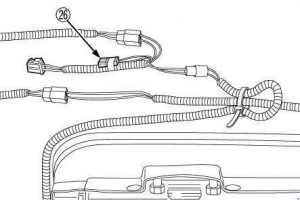
| 26 | 15 | Air suspension seat (if equipped) |

| Number | Amps [A] | Description |
| 1 | 15 | Working Light (right) |
| 2 | 15 | Work Light (left) |
| 3 | 5 | Alternator;
Engine; Glow plug. |
| 4 | 5 | Counter panel;
OPC. |
| 5 | 10 | Horn |
| 6 | 15 | Auxiliary power supply |
| 7 | 5 | Meter (backup) |
| 8 | 20 | Lighthouse;
Tail lamp. |
| 9 | 15 | Flicker (threat) |
| 10 | 5 | Startup Relay |
| 11 | 10 | Horn |

| Number | Amps [A] | Description |
| 12 | 40 | Key switch;
Headlight; Emergency Lights. |
| 13 | 30 | Fuel cut-off solenoid;
Operating light. |
| 14 | 50 | Loading;
Glow plug. |