
KIA Stinger – fuse box diagram
Year of manufacture: 2017, 2018, 2019, 2020, 2021, 2022.
Cigarette lighter fuse (power outlet) in the KIA Stinger Is the POWER OUTLET 1 fuse in the fuse box in the engine compartment.
Instrument panel (driver’s side)
Inside the fuse/relay covers is a fuse/relay label that describes the name and capacity of the fuse/relay.
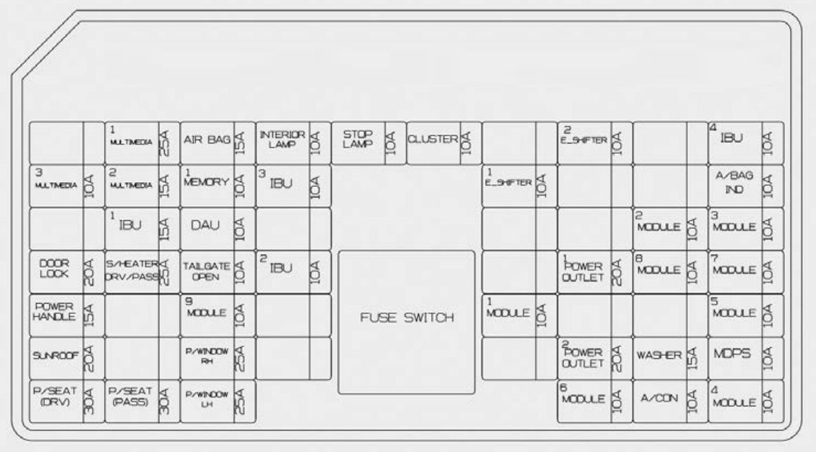
| Fuse name | Amps [A] | Description |
| MULTI MEDIA 1 | 25 | Low DC-DC Converter (Audio |
| AIR BAG | 15 | SRS control module (additional safety system) |
| INSIDE LAMP | 10 | Overhead console light;
Center interior light; Interior lamp; Night light switch; Left handle, right side of handle; Start light; Left handle, right side of handle; Glovebox light; Atmospheric light on driver and passenger door; Driver and passenger door light; Lamp with legroom. |
| STOP LAMP | 10 | IBU;
Stop light switch. |
| CLUSTER | 10 | Indicator set;
Upside-down screen. |
| E-SHIFTER 2 | 10 | Electronic transmission automatic gearshift lever (IG1) |
| IBU 4 | 10 | IBU (IG1) |
| MULTI MEDIA 3 | 10 | Indicator set;
Upside-down screen; Air conditioning switch. |
| MULTI MEDIA 2 | 15 | Audio |
| MEMORY 1 | 10 | Air conditioning control module;
Air conditioning switch; Safety indicator; Upside Up Screen. |
| IBU 3 | 10 | IBU (B +) |
| E-SHIFTER 1 | 10 | Electronic Transmission Shift Lever (B +) |
| A / BAG IND. | 10 | Indicator set;
Passenger airbag IND. |
| IBU 1 | 15 | IBU (B +) |
| DAU | 10 | Driver’s door module;
Driver and passenger exterior mirror (power). |
| MODULE 2 | 10 | IBU (IG2) |
| MODULE 3 | 10 | Transmission lever auto shift switch;
Driver’s door module; Stop light switch. |
| DOOR LOCK | 20 | Door lock relay;
Door Unlock; Two-turn unlocking relay. |
| S / HEAT DRV / PASS |
25 | Front fan seat control module;
Front seat heater control module. |
| TAIL GATE | 10 | Tailgate cover relay;
Fuel cap relay; Shock flap switch. |
| IBU 2 | 10 | Rain Sensor |
| POWER OUTLET 1 | 20 | Front power socket 2 |
| MODULE 8 | 10 | Cooling fan controller (BLDC motor);
Monitor all around; Front seat ventilation control module; Control module for heating the front and rear seats. |
| MODULE 7 | 10 | IBU;
ECS Unit; AWD (all-wheel drive); ECM (electronic control module); Intelligent cruise control module; Automatic transmission shift lever indicator; Switch on the console (forward/upward); Blind spot collision warning module; Left handle / right side handle; Steering wheel angle sensor; Steering wheel and telescope tilt module; Multifunction camera; Crash pad switch. |
| POWER HANDLE | 15 | Flywheel and telescope tilt module |
| MODULE 9 | 10 | Driver’s lumbar air control unit |
| MODULE 1 | 10 | Data link connector, console switch (top);
Ambient light control unit. |
| MODULE 5 | 10 | Air conditioning control module;
Air conditioning switch; Audio; Low-intensity DC-DC converter (audio / amplifier); Electrochromic mirror; Amplifier; Integrated memory controller circuit control module; Front seat ventilation control module; Control module for heating the front and rear seats. |
| SUNROOF | 20 | Opening roof (glass) control unit |
| P / WINDOW RH | 25 | Passenger window module;
Rear window module on the right side of the door handle. |
| POWER OUTLET 2 | 20 | Rear power socket |
| WASHER | 15 | Multifunction switch |
| MDPS | 10 | MDPS (power steering) module
(R-MDPS (power steering)) |
| P / SEAT (DRV) | 30 | Control module for the integrated driver memory system;
Driver’s seat module. |
| P / SEAT (PASS) | 30 | Passenger seat module |
| P/WINDOW LH | 25 | Driver window module;
Rear window ice. |
| MODULE 6 | 10 | IBU;
Low DC-DC converter (audio / amplifier); Electronic gear shift lever for automatic transmission (SBW (wire shift)); Wiring block in engine compartment (RLY. 4 – power take-off relay) |
| A / CON | 10 | Air conditioning control module;
Air conditioning switch; Connection block in engine compartment (blower relay). |
| MODULE 4 | 10 | AFS control unit;
Automatic headlight leveling module. |
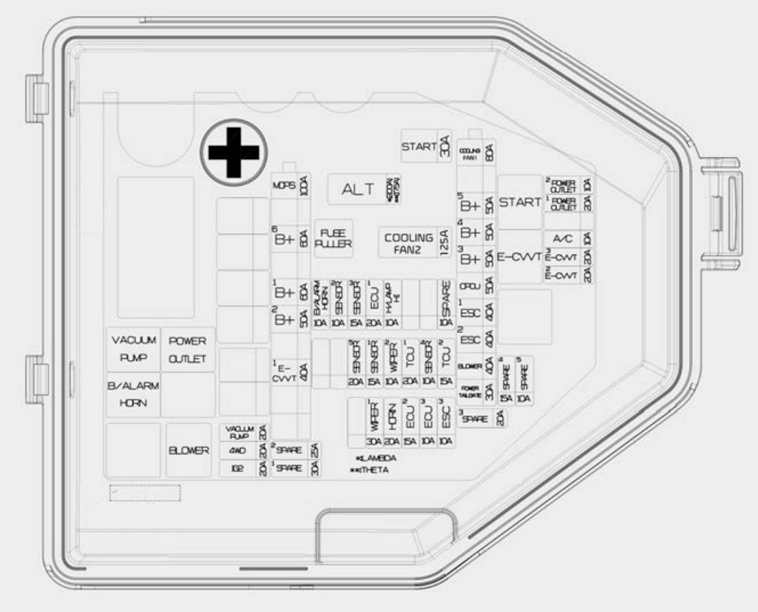
Fuse panel in engine compartment

| Fuse name | Amps [A] | Description |
| ALT | 175 | Alternator;
Multifuse fuse – COOLING FAN 1 / B+5 / B+4 /. B+3 / OPCU / ESC1 / ESC2 /. BLOWER / ELECTRIC TAILGATE. |
| 200 | ||
| COOLING FAN 2 | 125 | [BLDC (bezszczotkowy silnik prądu stałego)]
Cooling Fan Controller |
| START | 30 | Drive Relay |
| COOLING FAN 1 | 80 | [BLDC (bezszczotkowy silnik prądu stałego)]
Cooling Fan Controller |
| B + 5 | 50 | Instrument Panel Connector Block
(fuse – STOP LAMPS / Fuse leakage current – automatic shut-off device / LAMP INSIDE) |
| B + 4 | 50 | Instrument Panel Connector Block
(fuse -DOOR LOCK / POWER HANDLE / SUNROOF / FOR SEAT (DRV) / FOR SEAT (PASS)) |
| B + 3 | 50 | Instrument Panel Connector Block
(fuse – S/HEATER DRV/PASS / TAIL GATE / MODULE9 / P/WINDOW RH / P/WINDOW LH) |
| OPCU | 50 | Electric oil pump inverter |
| ESC 1 | 40 | ESC control module (Electronic Stability Control) |
| ESC 2 | 40 | ESC (electronic stability control) control module;
Universal control connector. |
| BLOWER | 40 | Blower relay |
| POWER BACK DOOR | 30 | Power Tail Gate Module |
| MDPS | 100 | MDPS unit (power steering) |
| B + 6 | 60 | Motor control relay;
Fuse – HORN / WIPER1 / H/LAMP H / B/ALARM HORN) |
| B + 1 | 60 | Instrument Panel Connection Block
(Fuse – IBU1 / IBU2) |
| B + 2 | 50 | Instrument Panel Connection Block
(fuse – E-SHIFTER1 / MODULE1) |
| E-CVVT 1 | 40 | [Silnik THETA II 2.0L T-GDI] E-CVVT relay |
| VACUUM PUMP | 20 | Vacuum pump relay |
| AWD | 20 | AWD (all-wheel drive) ECM
(electronic control unit) |
| IG 2 | 20 | IG2 Relay |
| POWER OUTLET 2 | 10 | Front/rear USB charger;
Front power socket #2. |
| POWER OUTLET 1 | 20 | Front power socket #1 |
| A / C | 10 | Air conditioning control module |
| E-CVVT 3 | 20 | [Silnik THETA II 2.0L T-GDI] ECM (engine control module) |
| E-CVVT 2 | 20 | [Silnik THETA II 2.0L T-GDI] ECM (engine control module) |
| ESC 3 | 10 | ESC (electronic stability control) control module;
Universal control connector. |
| 3 ECUS | 10 | ECM (engine control module) |
| 2 ECUS | 15 | ECM (engine control module) |
| HORN | 20 | Horn relay |
| WIPER 1 | 30 | Windshield wiper power relay |
| TCU 2 | 15 | TCM (Transmission Control Module) |
| SENSOR 4 | 10 | Brake vacuum switch;
Vacuum pump relay; Electric oil pump inverter. |
| TCU 1 | 20 | TCM (Transmission Control Module) |
| WIPER 2 | 10 | IBU (integrated body control unit);
ECM (electronic control module). |
| SENSOR 1 | 15 | Rear auxiliary connection block (fuel pump relay) |
| SENSOR 5 | 20 | [Silnik THETA II 2.0L T-GDI] Ignition coil #1 / #2 / #3 / #4;
[Silnik Lambda II 3.3L T-GDI] Ignition coil #1 / #2 / #3 / #4 / #5 / #6. |
| H / LAMP HI | 10 | Headlight Relay (High) |
| 1 ECU | 20 | ECM (engine control module) |
| SENSOR 3 | 15 | [Silnik THETA II 2,0 l T-GDI] Oxygen sensor (top);
[Silnik Lambda II 3,3 l T-GDI] Oxygen sensor #2 / #4. |
| SENSOR 2 | 10 | [Silnik THETA II 2.0L T-GDI]
Electronic thermostat; Oil control valve; Electromagnetic breather valve; RCV control solenoid valve (recirculation valve control); Canister shut-off valve [Silnik Lambda II 3.3L T-GDI] Electronic thermostat; Oil pressure solenoid valve; Oil control valve #1 / #2 / #3 / #4 (inlet / outlet); VCR (recirculation valve control) solenoid control valve; Explosion control; Solenoid valve; Canister shut-off valve. |
| B/ALARM HORN | 10 | Intruder alarm horn relay |
Relay
| Name of the courier | Type |
| Vacuum Pump Relay | ISO HC MICRO |
| B / Relay horn | ISO MICRO |
| Power Supply Output Relay | ISO HC MICRO |
| Blower relay | ISO HC MICRO |
| Start relay | ISO HC MICRO |
| E-CVVT relay (G4KL) | ISO MICRO |
Rear fuse box panel
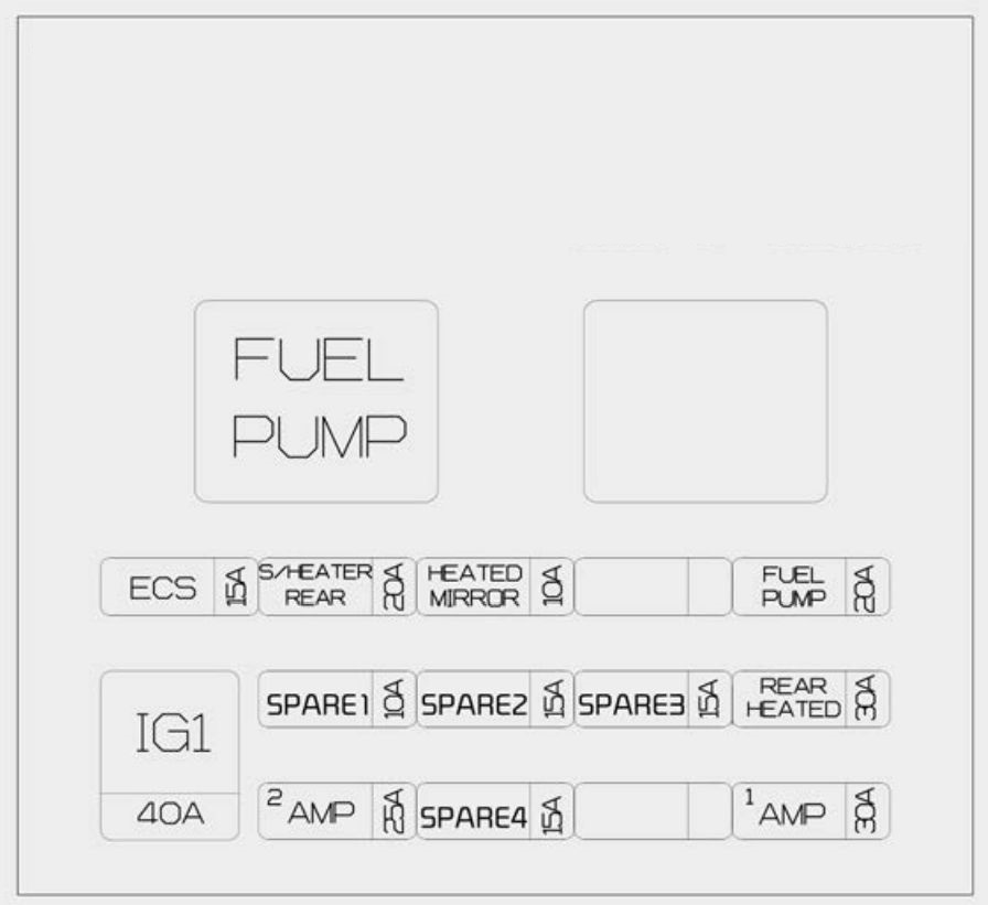
| Fuse name | Amps [A] | Description |
| ECS | 15 | ECS (Electronic Control Suspension) Unit |
| NO HEATER REAR |
20 | Rear seat heating control module |
| HEATED MIRROR |
10 | Air conditioning switch;
Driver and passenger exterior mirror (power). |
| FUEL PUMP | 20 | Fuel pump relay |
| SPARE1 | 10 | – |
| SPARE2 | 15 | – |
| SPARE3 | 15 | – |
| REAR HEAT | 30 | Heated rear relay |
| AMP 2 | 25 | AMP (amplifier) (MOBIS / PREMIUM) |
| SPARE4 | 15 | – |
| AMP 1 | 30 | Low DC-DC converter (amplifier) |
| IG 1 | 40 | IG1 / ACC Relay |
Battery terminal cover
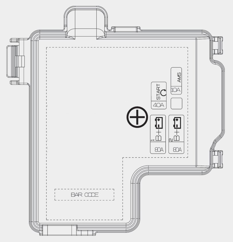
| Fuse name | Amps [A] | Description |
| B + 1 | 80 | Rear auxiliary connector block (fuse – FUEL PUMP / GROUND HEAT/ AMP1) |
| B + 2 | 80 | Rear auxiliary connector block (fuse – ECS / S/HEATER REAR / IG1) |
| START | 40 | Wiring block in engine room (power output relay), fuse -START / ECU2 / TCU1) |
| AMS | 10 | Battery sensor |