KIA Sportage (2014-2016) – fuse box diagram
Year of production: 2014, 2015, 2016.
Lighter fuse (electrical outlet) in Kia Sportage (2014-2016). is the fuse POWER OUTLET 2 in the fuse box.
Instrument panel

| Name(English). | Amp [A] | Description |
| POWER
CONNECTOR |
20 | Audio |
| 7,5 | RF Receiver | |
| A/BAG | 15 | SRS control module;
Passenger detection sensor; Warning light; SBR lamp. |
| S/HEATER
FRT |
15 | Heater Switch
driver/passenger seat |
| W/HEATER
RR |
15 | Rear seat heater LH/RH |
| A/CON | 7,5 | Air conditioning control module (automatic) |
| HTD
MIRR |
7,5 | Air conditioning control module;
Power supply for outdoor mirror driver/passenger |
| CLUSTER | 10 | Seat heating switch
driver/passenger; Driver CCS control module; Instrument cluster; Tire pressure monitoring module; Audio; Alternator; BCM, Air conditioning control module; Indicator light and SBR lamp |
| IG2 A | 10 | BCM;
Smart Key control module; IPS control module (IG2). |
| WIPPER
RR |
15 | Rear wiper motor;
Multi-function switch (windshield wiper); ICM relay module (rear wiper relay). |
| IG2 B | 10 | Cluster ionizer;
Air conditioning control module; Rain sensor; Sunroof motor; Electrochromic mirror; E/R fuse and relay box (Blower relay). |
| POWER
OUTLET 2 |
20 | Rear power socket;
Front power socket LH; Front cigarette lighter. |
| A / BAG IND | 10 | Airbag indicator kit no. |
| SMART
KEY 2 |
10 | Intelligent Key Control Module |
| WIPER
FRT |
25 | Front wiper motor;
Multifunction switch (windshield wiper); E/R fuse and relay box (Front windshield wiper relay (low), wiper relay (rain sensor)). |
| POWER
OUTLET 1 |
15 | Front power socket RH |
| SMART
KEY 1 |
10 | BCM;
Smart Key control module. |
| ACC | 10 | Audio, amplifier;
Sunroof control module; External outside mirror switch. |
| START | 10 | Anti-theft alarm relay
(with burglar alarm); E/R fuse and relay box (Starting relay: without anti-theft alarm and intelligent key), Intelligent Key Control Module (without anti-theft alarm and intelligent key). |
| MODULE
IG1 |
10 | EPS control module;
ATM ILL shift lever 4WD ECM; Stop light switch; IPS control module (IG1). |
| UH_BOX | 20 | E/R fuse and relay box
(ECU 2 7,5 A, ABS 7,5 A, TCU 2 7,5 A) |
| FOURTH LP | 10 | BCM;
Map Lamp; Living Room Lamp; Driver/passenger bathroom lamp; Electrochromic mirror; Luggage lamp; ILL ignition switch. ; Door warning switch; Tire pressure control module; Instrument cluster (MCU, IND.); Air conditioning control module; IPS control module (B +). |
| PDM B | 10 | Start/Stop button;
FOB handle; Smart Key control module. |
| DR LOCK | 15 | Door closing relay;
Door Unlocking; Tailgate relay; ICM relay module (two-speed unlocking relay). |
| HAZARD | 15 | BCM |
| FOG LP RR | 10 | – |
| PDM A | 25 | Intelligent Key Control Module |
| ATM
K/LOCK |
7,5 | ATM gear shift lever;
Key Electromagnet. |
| CORNERING
LAMP |
10 | – |
| HEADQUARTERS CENTER | 15 | CCS driver’s seat heater |
| P/WDW RH | 25 | Windshield lifter master switch;
Passenger window elevator switch; Right rear window lift switch. |
| P/WDW LH | 25 | LH rear window lift switch;
Main window elevator switch. |
| SAFETY
POWER WINDOW |
20 | Electrically controlled module
driver safety window |
| P / SEAT
(DRV) |
20 | Manual driver’s seat switch |
| MODULE B+ | 10 | Multifunction control connector;
Data link connector; Driver CCS switch; Rear parking assistance buzzer. |
| SUNROOF | 15 | Sunroof Engine;
Sunroof control module |
| AMP | 25 | Amplifier |
| HTD_STRG | 15 | Heated steering wheel |
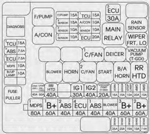
Engine compartment fuse panel


| Name (English) | Amp [A] | Description | |
| MULTI FUSE | MDPS | 80 | EPS control module |
| B + 1 | 60 | I/P Junction Box
(PDM A 25A, DR LOCK 15A, GAMBLING 15A, IPS 4 ~ 7) |
|
| ABS 2 | 40 | ESC Module | |
| EMS | 40 | EMS Box
(TCU 1 15A, ECU 30A, A/CON 10A, F/PUMP 15A). |
|
| ABS 1 | 40 | ESC Module | |
| BLOWER | 40 | Blower relay | |
| B + 3 | 60 | I/P junction box
(P/ SEAT (DRV) 20A, PDM B 10A, ATM K/LOCK 7.5A, SEAT OPENING 15A); Power connector (AUDIO 20A, RF_ANT 7.5A), LP ROOM 10A) |
|
| B + 2 | 60 | I/P junction box
(Windshield lift relay, ROOF 15A, AMP 25A, MODULE B + 10A, IPS 0 ~ 3, IPS 8 ~ 10) |
|
| FUSE | C/FAN
(MPI engine) |
40 | Cooling fan relay (high);
Cooling fan relay (low). |
| C/FAN
(T-GDI engine) |
50 | Cooling fan relay (high);
Cooling fan relay (low) |
|
| RR HTD | 40 | Rear defogger relay | |
| GI 1 | 30 | PDM relay box
(IGN1 / ACC relay: with smart switch); Ignition switch (without smart key) |
|
| IG 2 | 40 | PDM relay box
(IGN2 relay: with intelligent switch); Ignition switch (without smart key). |
|
| HORN | 15 | Horn relay | |
| DEICER | 15 | Front windshield wiper defrost relay | |
| STOP LP | 10 | Stop lamp switch;
Intelligent key control module; ICM relay module (DBC relay). |
|
| 4WD | 20 | ECM 4WD | |
| AMS | 10 | Battery sensor | |
| TCU 2 (MPI engine) | 7,5 | Transmission range switch | |
| TCU 2 (T-GDI engine) | 7,5 | Transmission range switch;
Vacuum switch; Vacuum pump relay. |
|
| ABS | 7,5 | ESC Module;
ICM relay module (DBC relay); Multifunction switch. |
|
| 2 ECUS | 7,5 | P/N ATM relay, PCM;
Multifunction switch (remote control). |
|
| V_PUMP (T-GDI engine). | 20 | Vacuum pump relay | |
Engine compartment main fuse panel (EMS Box)
| Name (English). | Amp[A] | Description |
| F / PUMP | 15 | Fuel Pump Relay |
| SENSOR 4 | 15 | Fuel pump relay;
PCM; Lambda probe (upper)/(lower); E/R fuse and relay box (cooling fan relay ). |
| SENSOR 3 | 10 | Relay A/CON;
Injector #1 ~ #4. |
| SENSOR 2 | 10 | – |
| TCU 1 | 15 | PCM |
| A / CON | 10 | Relay A / CON |
| SENSOR 1 (MPI engine) | 10 | Immobilizer module;
Crankshaft position sensor; Camshaft position sensor #1 / #2; Oil control valve #1 / #2; Solenoid valve Control the emptying of the can; Solenoid valve with variable inlet; Canister shut-off valve. |
| SENSOR 1 (T-GDI engine). | 10 | Immobilizer module;
Crankshaft position sensor; Camshaft position sensor #1 / #2; Oil control valve #1 / #2; Solenoid valve Control the emptying of the can; Solenoid valve with variable inlet; Canister shut-off valve; RCV. |
| 1 ECU | 20 | Ignition coil #1 ~ #4;
Condenser. |
| ECU | 30 | Motor control relay |


