Jeep Wrangler JK – Fuse box diagram
Year of manufacture: 2011, 2012, 2013, 2014, 2015, 2016.
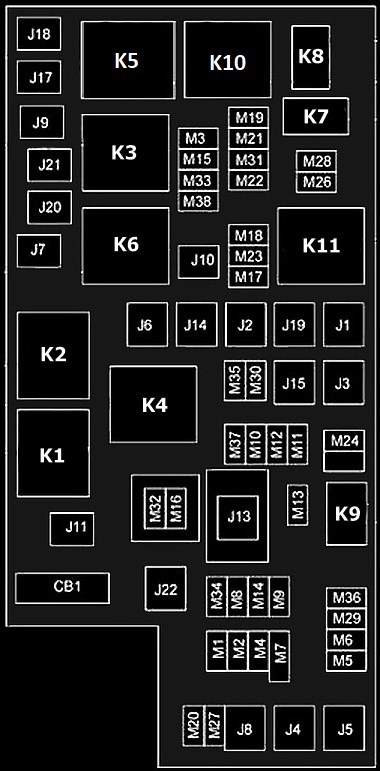
Fully integrated power supply module ( TIPM) is located in the engine compartment near the battery.
This center contains fuse cartridges, mini-fuses, and relays. A label identifying each component is printed on the inside of the cover.
| Depression | Cassette fuse | Mini fuse | Description |
|---|---|---|---|
| J1 | – | – | |
| J2 | 30 Amp Pink | Distribution Box Module | |
| J3 | – | – | |
| J4 | 25 Amp Natural | Driver’s door node | |
| J5 | 25 Amp Natural | Passenger door node | |
| J6 | 40 A green | Anti-lock braking system (ABS)/stability control pump | |
| J7 | 30 Amp Pink | Anti-lock braking system (ABS)/stability control valve | |
| J8 | – | – | |
| J9 | 40 A green | PZEV Sec/flexible fuel engine | |
| J10 | 30 Amp Pink | Headlight Washer Relay/Collector Tuning Valve | |
| J11 | 30 Amp Pink | Cross Stabilizer | |
| J12 | 30 Amp Pink | Rear Fan Motor/Fan | |
| J13 | 60 A yellow | Intake after switching off ignition switch (IOD) – main | |
| J14 | 40 A green | Rear window defroster | |
| J15 | 40 A green | Front Fan | |
| J17 | 40 A green | Starter Solenoid | |
| J18 | 20 A blue | Powertrain Control Module (PCM);
Gearbox Range |
|
| J19 | 60 A yellow | Radiator Fan | |
| J20 | 30 Amp Pink | Front Windshield Wiper | |
| J21 | 20 A blue | Front/rear washer | |
| J22 | – | Reservation | |
| M1 | 15 A blue | Height Mounted Stop Light Central Switch (CHMSL)/Stop Light Power Switch | |
| M2 | 20 A yellow | Trailer relay light (stop light) | |
| M3 | 20 A yellow | Front/rear axle lock relay | |
| M4 | – | – | |
| M5 | 25 Amp Natural | Power Inverter – if equipped | |
| M6 | 20 A yellow | Electrical socket 1;
Rain sensor. |
|
| M7 | 20 A yellow | Power socket 2 | |
| M8 | 20 A yellow | Front heated seat | |
| M9 | 20 A yellow | Heated rear seat – if equipped | |
| M10 | 15 A blue | Ignition off – car entertainment system, digital satellite audio receiver (SDARS), DVD, hands-free module, RADIO, antenna, universal garage door opener, bathroom light | |
| M11 | 10 A red | (Ignition off) Climate control system, lamp under bonnet | |
| M12 | 30 A green | Amplifier | |
| M13 | 20 A yellow | Off-take ignition – cab compartment node, wireless control module, SYRENA, multifunction control switch | |
| M14 | 20 A yellow | Towing a trailer (export only) | |
| M15 | 20 A yellow | Climate control system, rear view mirror, cabin compartment node, dashboard switch, multifunction control switch, tire pressure monitor, glow plug module – diesel export only | |
| M16 | 10 A red | Airbag module | |
| M17 | 15 A blue | Left tail lamp/license/parking | |
| M18 | 15 A blue | Right tail lamp/parking/running | |
| M19 | 25 Amp Natural | Auto Power Off (ASD #1 and #2) | |
| M20 | 15 A blue | Car interior lighting, switch assembly | |
| M21 | 20 A yellow | Auto power off (ASD #3) | |
| M22 | 10 A red | Right (High/Low) horn | |
| M23 | 10 A red | Left (High/Low) horn | |
| M24 | 25 Amp Natural | Rear Windshield Wiper | |
| M25 | 20 A yellow | Fuel Pump, Diesel Lift Pump – Export only | |
| M26 | 10 A red | Window switch, driver’s window switch | |
| M27 | 10 A red | Ignition switch power supply, wireless module | |
| M28 | 10 A red | Drive Train Control Module | |
| M29 | 10 A red | Drive system | |
| M30 | 15 A blue | Front wiper motor, diagnostic cable J1962 | |
| M31 | 20 A yellow | Replacement lamps | |
| M32 | 10 A red | Airbag controller, TT EUROPE | |
| M33 | 10 A red | Powertrain Controller | |
| M34 | 10 A red | Park assist, air conditioning system, headlight washer, compass | |
| M35 | 10 A red | Heated mirrors | |
| M36 | 20 A yellow | Power socket | |
| M37 | 10 A red | Anti-lock braking system, electronic stability control, stop light switch, fuel pump relay | |
| M38 | 25 Amp Natural | Engine Lock/Unlock |
Relay
| Number | Description |
|---|---|
| K1 | Ignition (work/accessories) |
| K2 | Ignition (operation) |
| K3 | Starter |
| K4 | Ignition (Run-Start) |
| K5 | Transmission Control Module (TCM) |
| K6 | Rear window (hard top) |
| K7 | Not used |
| K8 | Not used |
| K9 | Not used |
| K10 | Auto power off |
| K11 | Radiator Fan Control |