Fuse diagrams and relay boxes – Jaguar F-Type
Applies to vehicles manufactured over the years:
2014, 2015, 2016, 2017.
Location of fuse boxes
The vehicle has 6 separate fuse boxes, each containing fuses to protect a different group of circuits.
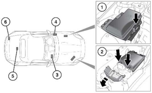
- Fuse box on the left side of the engine compartment:
Remove the left side cover under the cover, press the clamp to release the fuse box cover.
- Fuse box on the right side of the engine compartment:
Open the side cover and press the 2 clamps to release the fuse box cover.
- Fuse box in the passenger compartment, located in the leg compartment on the passenger side:
Pull the carpet/carpet back to expose the access panel. Pull back and remove the access panel to view the fuse box.
- Fuse box in the passenger compartment, located on the left A-pillar under the dashboard:
Unscrew the access panel to view the fuse box.
- Coupe cars only:
The fuse box is accessed by: Folding down the trunk floor panel and removing the floor panel bracket. Removing the left side trunk lid (battery). Removing the trunk lid.
- Convertibles only.
The fuse box is accessed by: Removing the left (battery) side of the trunk lid. Removing the trunk lid.
Removing the covers under the hood:
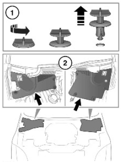
- Turn the handle screws counterclockwise, then pull to remove.
- Lift the front edge of the cover and push forward to remove.
- Install these parts in the reverse order of removal.
Fuse boxes in passenger compartment
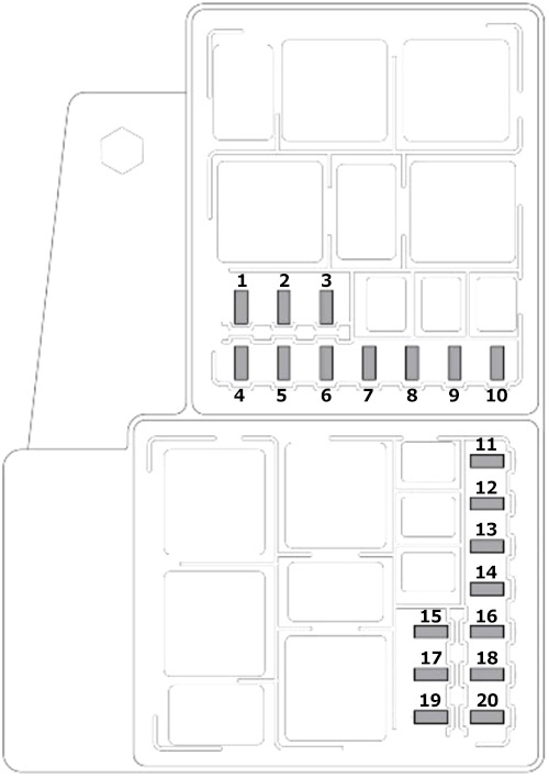
Diagram of the A-pillar fuse box on the left
| Number | Amps [A] | Description |
|---|---|---|
| F1 | 30A | Electric Parking Brake (EPB) (left side) |
| F2 | – | – |
| F3 | – | – |
| F4 | – | – |
| F5 | 10 A | Instrument panel control, instrument panel fan |
| F6 | 15A | Folding roof (front latch) |
| F7 | – | – |
| F8 | 5A | Keyless vehicle module (logic) |
| F9 | 15A | Folding roof (bottom lock) |
| F10 | 10 A | A/C Clutch |
| F11 | 25A | Heated front seat |
| F12 | 5A | Seat switch power |
| F13 | 10 A | Chassis control module (spoiler), JaguarDrive control switch |
| F14 | – | – |
| F15 | 25A | Trunk |
| F 16 | 30A | Electric Parking Brake (EPB) (right side) |
| F17 | 10 A | Adaptive damping control, chassis control module |
| F18 | – | – |
| F19 | 30A | Fuel Pump |
| F20 | – | – |
| F21 | 10 A | Rear view camera, headlights, blind spot monitoring (BSM), parking distance control, interior mirror |
| F22 | 5A | Right-side reflector motor |
| F23 | 5A | Left-side reflector motor |
| F24 | 5A | Headlight Leveling |
| F25 | 10 A | Instrument panel control, instrument panel fan |
| F26 | 5A | Gateway Module |
| F27 | – | – |
| F28 | – | – |
| F29 | 10 A | Rear view camera, headlights, blind spot monitoring (BSM), parking distance control, interior mirror |
| F30 | 5A | Normal mode (or transport mode) |
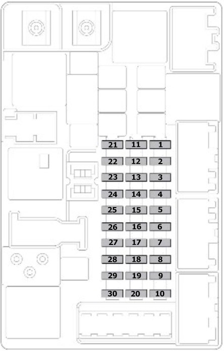
Passenger side fuse box diagram
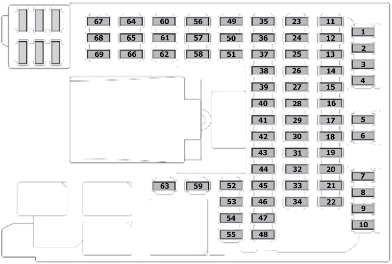
| Number | Amps [A] | Description |
|---|---|---|
| F1 | 5A | Radio frequency (RF) receiver, internal motion sensor, tire pressure monitoring sensor (TPMS) |
| F2 | – | – |
| F3 | – | – |
| F4 | 5A | CAN gateway module |
| F5 | 5A | Anti-lock braking system (ABS), steering angle sensor |
| F6 | – | – |
| F7 | – | – |
| F8 | 30A | Right-hand seat (delivery 2) |
| F9 | 5A | Electric Parking Brake (EPB) |
| F10 | 5A | Adaptive Damping Control |
| F11 | – | – |
| F12 | 5A | Reversing lights and closing with mirror dimming |
| F13 | – | – |
| F14 | 5A | Brake pedal switch |
| F15 | 30A | Heated rear window |
| F 16 | – | – |
| F17 | – | – |
| F18 | – | – |
| F19 | 5A | Powertrain control module, electronic control module |
| F20 | 10 A | Heated steering wheel |
| F21 | 10 A | Passenger airbag deactivation lamp (upper console) |
| F22 | 5A | Gearbox control module, rear differential, electronic gearbox switch (ignition signal) |
| F23 | 5A | Fuse box suppression |
| F24 | 5A | Right Rear Fog Light |
| F25 | 5A | Rear fog light on left side |
| F26 | – | – |
| F27 | – | – |
| F28 | 25A | Door Module (right side) |
| F29 | – | – |
| F30 | – | – |
| F31 | 5A | Rain sensor, air conditioning sensors |
| F32 | 25A | Door Module (left side) |
| F33 | – | – |
| F34 | 10 A | Locker Locker |
| F35 | – | – |
| F36 | – | – |
| F37 | – | – |
| F38 | 15A | Windshield washer |
| F39 | – | – |
| F40 | – | – |
| F41 | – | – |
| F42 | 30A | Left-hand seat (delivery 1) |
| F43 | 10 A | Active exhaust |
| F44 | – | – |
| F45 | 30A | Right-hand seat (delivery 1) |
| F46 | 30A | Left-hand seat (delivery 2) |
| F47 | – | – |
| F48 | – | – |
| F49 | – | – |
| F50 | – | – |
| F51 | 5A | Flywheel switches |
| F52 | 20A | Accessory socket (center) |
| F53 | 20A | Socket / Lighter Accessory (box) |
| F54 | – | – |
| F55 | – | – |
| F56 | 10 A | Immobilization control module |
| F57 | 10 A | Storage compartment, reading lamps |
| F58 | – | – |
| F59 | 10 A | Soft closing of the door (close and reverse) |
| F60 | 5A | Presence Monitoring Sensor |
| F61 | 5A | Immobilizer Antenna |
| F62 | – | – |
| F63 | – | – |
| F64 | – | – |
| F65 | – | – |
| F66 | – | – |
| F67 | – | – |
| F68 | – | – |
| F69 | – | – |
Fuse boxes in the engine compartment
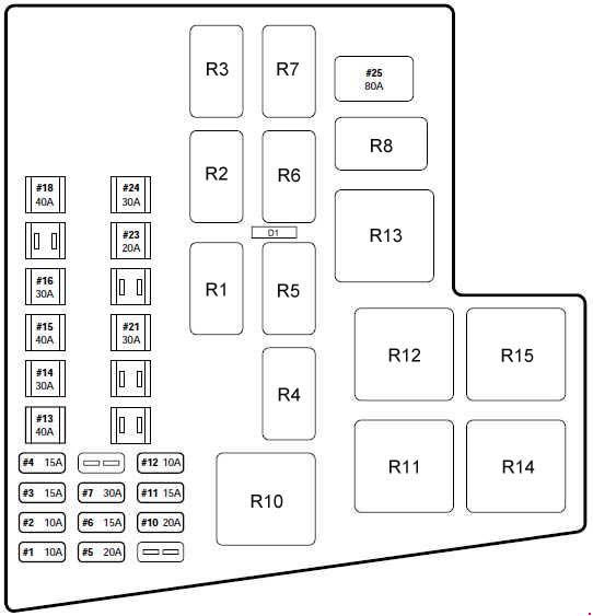
Diagram of the left side fuse box
| Number | Amps [A] | Description |
|---|---|---|
| F1 | 5A | Diagnostic Socket |
| F2 | 20A | Washer transfer pump |
| F3 | – | – |
| F4 | 5A | Monitor (starter motor monitoring) |
| F5 | 25A | Engine Management (Ignition Coils) |
| F6 | 5A | Engine management (MAF sensors) |
| F7 | 5A | Motor management (sensors) |
| F8 | 10 A | Motor management (actuators) |
| F9 | 10 A | Motor management (throttle motor) |
| F10 | 15A | Engine management (variable valve timing) |
| F11 | 20A | Engine Management (left side of oxygen sensor) |
| F12 | 20A | Engine management (oxygen sensor on the right side) |
| F13 | 20A | Engine management (catalytic converter oxygen sensor) |
| F14 | 10 A | Electric water pump |
| F15 | 5A | Active exhaust valve |
| F 16 | – | – |
| F17 | 5A | Engine Management System |
| F18 | 30A | Antilock Brake System Valves (ABS) |
| F19 | 15A | Electronic gearbox switch, gearbox control module |
| F20 | 30A | Four-wheel drive system |
Diagram of the right side fuse box
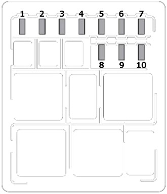
| Number | Amps [A] | Description |
|---|---|---|
| F1 | 25A | Headlight Washer |
| F2 | – | – |
| F3 | 15A | Horn |
| F4 | – | – |
| F5 | – | – |
| F6 | – | – |
| F7 | – | – |
| F8 | – | – |
| F9 | – | – |
| F10 | – | – |
Trunk fuse box diagram
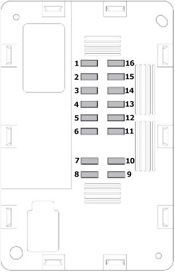
| Number | Amps [A] | Description |
|---|---|---|
| F1 | 15A | Touch screen, front integrated control panel |
| F2 | 10 A | Sound amplifier |
| F3 | – | – |
| F4 | 10 A | Satellite radio, navigation system |
| F5 | 15A | Audio Head Unit |
| F6 | 15A | Audio/Video Input/Output Panel |
| F7 | – | – |
| F8 | – | – |
| F9 | – | – |
| F10 | – | – |
| F11 | – | – |
| F12 | – | – |
| F13 | – | – |
| F14 | – | – |
| F15 | 15A | Front integrated control panel (heating and ventilation) |
| F 16 | – | – |