
Fuse diagram and relay box – Isuzu Amigo
Applies to new vehicles in years:
1998, 1999, 2000, 2001, 2002, 2003, 2004.
Location
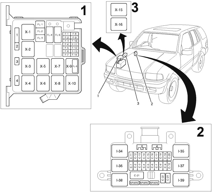
- Fuse and relay box (engine room)
- Fuses and relay box (instrument panel)
- Relay box (engine room)
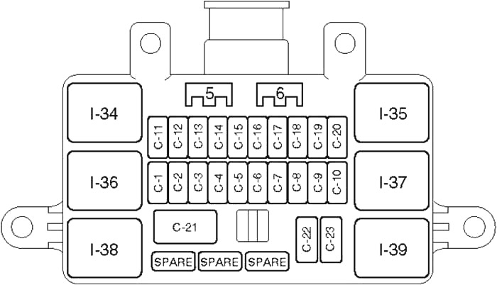
Switchboard fuse box diagram
The fuse box is located behind the driver side cover of the instrument panel.
| Number | Amps [A] | Description |
| C1 | 20 | Accessory socket relay, accessory socket |
| C2 | 10 | Audio |
| C3 | 15 | Lighter |
| C4 | 15 | Rear relay, Parking light and side marker light, Tail light, License plate light, Lighting controller, Illumination light, Control unit for all gear shift indicators |
| C5 | 10 | Stop light, dome light, left ceiling light, right ceiling light, left rear ceiling light, right rear ceiling light, start light, alarm and relay control unit, digital clock, sound |
| C6 | 15 | Stop light switch, rear combination light – left, rear combination light – right, height mounted stop light |
| C7 | 20 | Front door lock and electric window, door lock actuator, anti-theft indicator; |
| C8 | 10 | Defroster Mirror |
| C9 | 15 | Rear fog |
| C10 | 15 | Rear fog |
| C11 | 15 | Warning lights and lamps (meter), meter, vehicle speed sensor |
| C12 | 15 | Generator, ECM main relay, vacuum switching valve (VSV); bleed solenoid valve, solenoid drive, powertrain module (PCM), EGR valve |
| C13 | 15 | Ignition Coil |
| C14 | 15 | SW mode, PCM, indicator, reverse light, cruise control, A/T gear indicator control unit |
| C15 | 15 | Alarm control unit and relay, rear defroster relay, left mirror defroster, right mirror defroster, rear window defroster, power window relay, cruise control unit, shift lock relay, 4WD control unit, vacuum interrupter valve (VSV); FRT shaft (c), vacuum interrupter valve (VSV); FRT shaft (d) |
| C16 | 20 | Windshield wiper motor, windshield washer motor, alarm and relay control unit |
| C17 | 10 | Rear wiper motor, rear window washer motor, alarm and relay and control unit |
| C19 | 15 | Audio |
| C20 | 10 | Starter, starter relay, anti-theft controller |
| C21 | 30 | Windshield lift relay, Windshield switch, Windshield motor, Roof opening motor, Roof control unit, Roof switch, Safety switch, Limiter switch, Switch seatFront tilt motor and SW, Rear tilt motor and SW, Slide motor, Recliner motor & SW |
| C22 | 10 | SRS, SDM Warning Light |
| Relay | ||
| I34 | Tail lights | |
| I35 | Window Supply | |
| I36 | – | |
| I37 | – | |
| I38 | Accessory socket | |
| I39 | Rear fog | |
| LED | ||
| 5 | SW rear door, SW doors, interior light | |
| 6 | Alarm and relay control unit | |
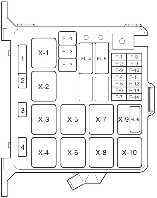
Diagram of the fuse box in the engine compartment
| Number | Amps [A] | Description |
| F1 | 15 | Hazard Warning Light |
| F2 | 10 | Alarm and relay control unit, horn, anti-theft horn |
| F4 | 20 | Blower motor, blower heater |
| F5 | 10 | A/C thermostatic relay, electronic thermostat, A/C compressor relay, magnetic clutch |
| F8 | 10 | Headlight – left, high beam indicator, fog light relay |
| F9 | 10 | Lighthouse – on the right |
| F10 | 15 | Fog Lights |
| F11 | 20 | Oxygen sensor |
| F12 | 20 | Fuel Pump |
| F13 | 15 | Motor control module |
| F14 | – | – |
| FL1 | 60 | EHCU |
| FL2 | 30 | 6VD1: Condenser fan |
| FL4 | 100 | Ignition switch, starter relay, air conditioning, generator, heating relay, Fuse: F10, FL1, FL2, FL5, FL6 |
| FL5 | 60 | Ignition switch, fuel pump relay, engine control module relay, drive train module |
| FL6 | 30 | X22SE: Electric fan relay, electric fan |
| Relay | ||
| X1 | Headlight | |
| X2 | Fog lamps | |
| X3 | Starter | |
| X4 | A/C Compressor | |
| X5 | Thermo | |
| X6 | Heater | |
| X7 | Fuel Pump | |
| X8 | Engine control module | |
| X9 | 6VD1: Condenser fan | |
| X10 | – | |
| Diode | ||
| 1 | Brake | |
| 2 | – | |
| 3 | – | |
| 4 | – | |
| Relay Box | ||
| X15 | X22SE: Cooling fan (high speed) | |
| X16 | X22SE: Cooling fan (low speed) | |