Infiniti QX70 (S51, 2008-2017) – fuse box diagram
Year of production: 2008, 2009, 2009, 2010, 2011, 2012, 2013, 2014, 2015, 2016, 2017
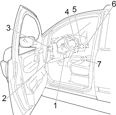
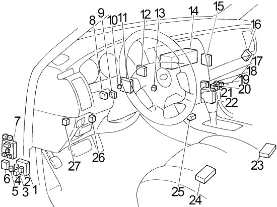
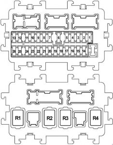
Panel fuse panel (J / B).
| Number | FOR | Description |
| 1 | – | – |
| 2 | 10 | Passenger detection system control unit Airbag diagnostic sensor |
| 3 | 10 | Front Combination Lamp RH Front Lamp LH Ionizer combo acclimatized seat relay Unified air conditioning meter and amplifier. Low tire pressure warning control unit Can Gateway AV Control Unit Exhaust gas/external odor sensor Automatic anti-glare interior mirror ICC courier Brake Stop Switch ASCD Brake Stop Switch stop light AFS control unit Data Link Connector Warning Systems Switch Lane Departure Warning Buzzer Lane camera module Adapter mounting Tel. Compressors Heated seat relay Heated seat switch (driver’s side) Heated seat switch (passenger’s side) |
| 4 | 10 |
Combined counter backup lamp relay View around the monitor unit Sonar Control Unit |
| 5 | 20 | Accessory Relay |
| 6 | 10 | Key / socket Clock Data Link Connector Rain Sensor Intelligent warning key Buzzer Automatic anti-glare interior mirror |
| 7 | 10 | Light switch body control module ICC Brake Relay Stop (BCM) |
| 8 | 20 | Bose (audio system) |
| 9 | 10 | Push-button ignition switch in key slot |
| 10 | 10 | Body Control Module (BCM) Automatic drive position controller Control unit Control unit. full illumination Memory Switch Seats Drive seat control unit |
| 11 | 10 | Counter on Unified meter and air conditioning amplifier. AWD control unit CAN Port Pre-crash seat belt control unit (driver/passenger side) |
| 12 | – | Reservation |
| 13 | – | Reservation |
| 14 | – | – |
| 15 | 10 | Exterior mirrors |
| 16 | 20 | Rear window defogger |
| 17 | 20 | Rear window defogger |
| 18 | 10 | E-SUS control unit |
| 19 | – | – |
| 20 | 15 | Front power socket |
| 21 | 10 | Remote control switch for side mirror Unified air conditioning meter and amplifier. Multifunction switch Full Lighting Control Unit AV Around the Sight Monitoring Control Unit adapter Tel. Satellite Tuner |
| 22 | 20 | Console power socket Rear power socket |
| 23 | 15 | Fan motor |
| 24 | 15 | Fan motor |
| 25 | – | Reservation |
| 26 | – | Reservation |
| Relay | ||
| R1 | Ignition Relay | |
| R2 | Rear windscreen defroster relay | |
| R3 | Accessory Relay | |
| R4 | Blower relay | |
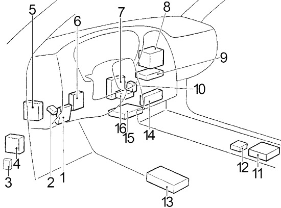
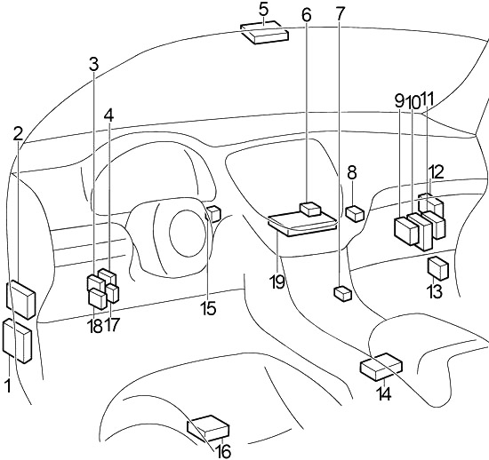
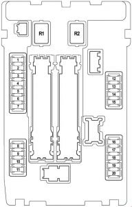
Fuse box in engine compartment (IPDM E / R)
| Number | FOR | Description |
| 1 | 15 | Relay pump Fuel Pump Control Module Mounting the fuel level sensor Fuel Pump Engine Control Module (ECM) |
| 2 | 10 | Cooling fan relay 2 |
| 3 | 10 | Transmission control module (TCM) snow mode switch |
| 4 | 10 | Fuel injector 1 Injector No. 2 Injector No. 3 Injector No. 4 Injector No. 5 Injector No. 6 Injector no. 7 (VK engine) Injector No. 8 (VK engine) Engine Control Module (ECM) Body Control Module (BCM). Full Lighting Control Unit |
| 5 | 10 | Integrated ICC Sensor Assembly Accelerator Pedal Actuator ABS and electrical unit (unit control unit ) Angle sensor Steering angle sensor 1 Lateral sensor G AWD control unit Power Steering Control Unit RAS control ICC amplifier beeper Brake Control Unit |
| 6 | 15 | Heated oxygen sensor 2 (Bank 2) Heated Oxygen Sensor 2 (Bank 1) Air/Fuel Ratio (A/F) Sensor 1 (Bank 1) Air/fuel ratio (A/F) Sensor 1 (Bank 2). |
| 7 | 10 | Combination Switch |
| 8 | – | – |
| 9 | 10 | A/C relay compressor |
| 10 | 15 | ECM relay Engine Control Module (ECM) Condenser Valve time control solenoid valve Intake Time Control Solenoid Valve (row 1) Intake valve timing control solenoid valve (row 2) Exhaust valve timing control solenoid valve (Bank 1) Exhaust valve timing control solenoid valve (Bank 2) EVAP absorption vent control valve. Ignition coil #1 (with power transistor) Ignition Coil #2 (with power transistor) Ignition Coil #3 (with power transistor) Ignition Coil #4 (with power transistor) Ignition Coil No. 5 (with power transistor) Ignition Coil #6 (with power transistor) Ignition coil no. 7 (with power transistor; VK engine) Ignition coil no. 8 (with power transistor; VK engine) Solenoid valve for EVAP absorber blowing volume regulation Air mass flow sensor (row 2) Air mass flow sensor ( line 1) VVEL control module |
| 11 | 15 | Relay Throttle motor control module (ECM) |
| 12 | 10 | LH front combination lamp (back lamp) RH front combination lamp (tail lamp) |
| 13 | 10 | LH combined taillight Rear combination lamp RH Lamp. License plate LH License plate LH LIGHT. License plate lamp gloves Full Lighting Control Unit Front power socket ATT switch AV Control Unit |
| 14 | 10 | LH front combination lamp (high beam) |
| 15 | 10 | Front Combination Lamp RH (High Beam) |
| 16 | 15 | Headlight LH (Low beam) |
| 17 | 15 | RH Headlight (Low Beam) |
| 18 | 10 | Front fog light relay (LH front fog light, RH front fog light) |
| 19 | – | – |
| 20 | 30 | Front wiper relay |
| Relay | ||
| R1 | – | |
| R2 | Start Control Relay | |
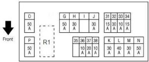
Engine compartment fuse box (E12)
| Number | FOR | Description |
| 31 | 15 | Horn relay 1 Alternator |
| 32 | 30 | Optional connector |
| 33 | 10 | AWD unit brake assist control unit |
| 34 | 15 | Front View Display Unit AV Controls Around the Sight Monitoring Control Unit Subwoofer Speaker Satellite radio tuner Tel Adapter |
| 35 | – | – |
| 36 | 10 | Transmission Control Module (TCM) |
| 37 | 20 | Motor relay RAS |
| 38 | 10 | Horn relay 2 |
| sun | 50 | Actuator VVEL motor relay |
| H. | 30 | Fuse block J / B IPDM E / R |
| I | – | – |
| jot | 30 | Pre-crash seat belt control unit (driver’s side) |
| K. | 30 | Pre-crash seat belt control unit (passenger side) |
| L | 40 | Body Control Module (BCM) Automatic driving positioner Cont Driver’s seat control unit Lumbar support switch Screw side Electric seat switch |
| M | 30 | ABS actuator and electronic unit |
| N | 50 | ABS actuator and electronic unit |
| O | 50 | Cooling fan relay 1 |
| P. | 50 | Fuse block E213 – fuse no.: Q (automatic tailgate control unit), 61 (accelerator pedal actuation), 62 (air-conditioning controlled seat relay), 63 (air-conditioning controlled seat relay, heated seat relay) |
| Relay | ||
| R1 | Horn relay 1 | |
Fuse block on the positive terminal of the battery
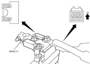
| Number | FOR | Description |
| FOR | 250 | Fuse No. alternator starter : C. D, E |
| b | 100 | Fuse no: O (cooling fan relay 1), S (cooling fan relay 2) |
| For | 100 | Fuse and Fuse Connection Block |
| re | 80 | Fuse block J / B (fuse numbers: 5, 6, 7, 8, 9, 10, 11) For additional power supply For ignition power supply |
| mi | 100 | IPDM E / R (fuse number: 10, 11) to the ignition power source |
| fa | 60 | IPDM E / R (fuse no: 18 (front fog light relay); high beam relay, low beam relay, tail light relay) for ignition power supply |
Fuse box in engine compartment (E212; VK engine)
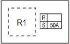
| Number | FOR | Description |
| R | – | – |
| S | 50 | Cooling Fan Relay 2 |
| Relay | ||
| R1 | Cooling fan relay 2 | |
Engine compartment fuse box (E213)

| Number | FOR | Description |
| 61 | 15 | Accelerator pedal actuator |
| 62 | 15 | Weather controlled seat relay |
| 63 | 10 | Weather controlled seat relay heated seat |
| Q | 30 | Automatic tailgate control unit |
| Relay | ||
| R6 | Horn relay 2 | |
| R8 | ICC Brake Holding Relay | |