Fuse and relay box diagrams – Infiniti M45
Applies to vehicles manufactured over the years:
2003, 2004.
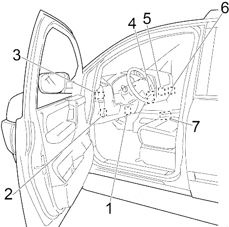
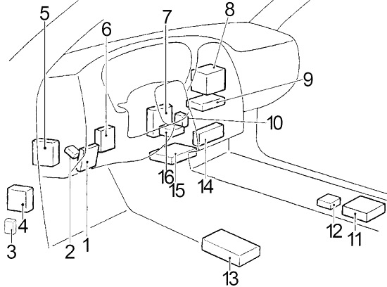
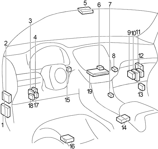
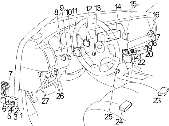
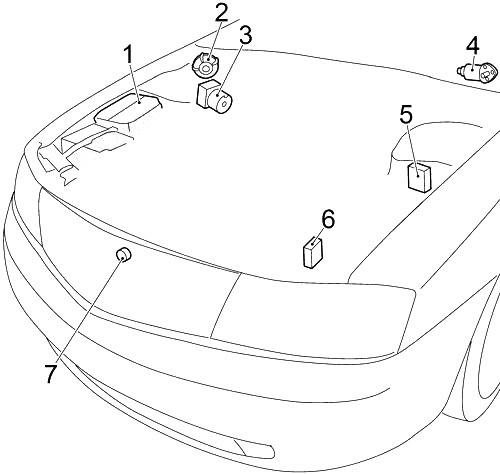
Passenger compartment
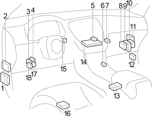
- Body Control Module (BCM)
- Fuse box №1
- Nissan Anti-Theft System Immobilizer (NATS)
- Headlight battery saving control unit
- Low tire pressure warning control unit
- Combined flash unit
- Power steering control unit
- Automatic air conditioning boost
- Engine Control Module (ECM)
- Transmission control module (TCM)
- VDC/TCS/ABS control unit
- Fuse box №2
- Airbag diagnostic sensor unit
- AV control unit
- Steering wheel lock control unit
- Driver’s seat control unit
- Shift closing control unit
- Automatic Speed Control Unit (ASCD)
The two fuse blocks are located at the bottom behind the foot panel on the driver and passenger side.
Passenger compartment fuse box №1 Diagram.
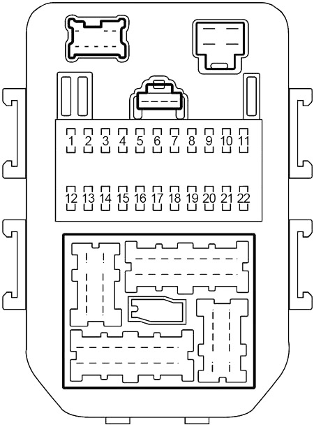
| Number | Amps [A] | Description |
|---|---|---|
| 1 | 10 | Body control module (BCM), intelligent cruise control (ICC) audible warning, ICC sensor, ICC unit, ICC brake stop relay, AV and Navi control unit, NATS IMMU, automatic anti-glare interior mirror, Homelink universal transceiver, headlight battery saver Control unit, rear window defroster relay, dual function muffler control unit, exterior mirror, air conditioning seat relay, air conditioning seat control unit (driver/passenger side) |
| 2 | 10 | Automatic air conditioning booster, ECV solenoid valve (air conditioning compressor) |
| 3 | 10 | Body control module (BCM), trunk lid opening relay |
| 4 | 10 | Remote control switch for exterior mirrors, handset, exterior mirror defroster relay |
| 5 | 10 | Flash drive on |
| 6 | 10 | Data link connector, Combination counter, Automatic air conditioning amplifier, Headset, Low tire pressure warning control unit, Safety light, Body control module (BCM), NATS IMMU, Steering lock control unit, Warning signal, Headlight battery saving control unit, Clock |
| 7 | 10 | VDC/TCS/ABS control unit, power steering control unit |
| 8 | 10 | Driver/passenger side mirror control, automatic anti-obstruction interior rear view mirror, Homelink universal transceiver, ignition lamp with key hole, map lights, console lamp, rear personal lamp, front step lamps, rear step lamps, cosmetic mirror lamp, trunk lamp, seat memory switch |
| 9 | 10 | Combination meter, spare bulb relay, alternator |
| 10 | 20 | Rear window defroster relay, door mirror defroster relay |
| 11 | 20 | Rear window defroster relay, door mirror defroster relay |
| 12 | 10 | Automatic speed control unit (ASCD), ASCD brake switch, shift lock control unit |
| 13 | 15 | Fuel injectors, engine control module (ECM), fuel pump relay |
| 14 | 10 | Starting system, engine control module (ECM), body control module (BCM), daytime running light control unit |
| 15 | 10 | Trunk lock control unit, trunk lid opening actuator, fuel lid opening actuator |
| 16 | 10 | Heated oxygen sensors |
| 17 | 15 | Stop light switch, intelligent cruise control (ICC) stop relay, A/T device, VDC/TCS/ABS control unit |
| 18 | 10 | Heated oxygen sensors |
| 19 | 10 | – |
| 20 | 10 | Airbag diagnostic sensor unit |
| 21 | 10 | Audio unit, BOSE speaker amplifier, automatic CD changer, satellite radio receiver, AV and Navi control unit, display, multifunction switch, voice-activated control module, low tire pressure warning control unit, automatic air conditioning amplifier, fan motor relay, body control module (BCM), combination meter |
| 22 | 15 | Flash drive on |
| R1 | Accessory | |
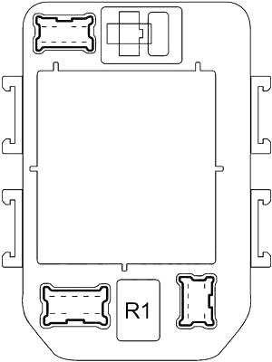
Passenger compartment fuse box №2 Diagram
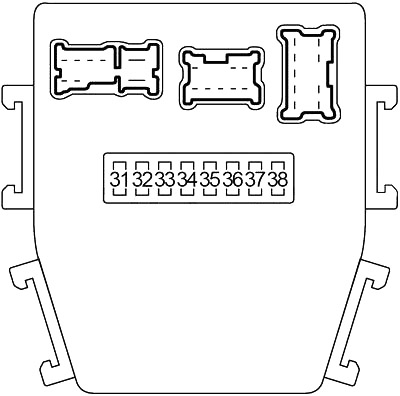
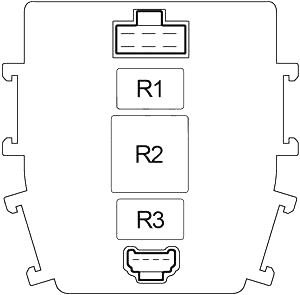
| Number | Amps [A] | Description |
|---|---|---|
| 31 | 15 | Fan motor |
| 32 | 10 | Ignition switch and key lock solenoid, engine control module (ECM) relay (intake valve timing control position sensor, mass air flow sensor, crankshaft position sensor, crankshaft position sensor), transmission control module (TCM), A/T PV IGN relay, IMMU . NATS |
| 33 | 15 | Fan motor |
| 34 | 20 | Front wiper relay, front wiper motor, front washer motor |
| 35 | 10 | Transmission control module (TCM), A/T PV IGN relay |
| 36 | 15 | Fuel Pump Relay |
| 37 | 10 | Device |
| 38 | – | – |
| R1 | Blower | |
| R2 | Engine Control Module (ECM) | |
| R3 | Fuel Pump | |
Engine compartment
- Fuse box
- Pump with automatic speed control device (ASCD)
- VDC Actuator
- Front wiper motor
- VDC relay box
- Daylight Control Unit
- Hood switch
Diagram of the fuse box in the engine compartment
Near the battery.
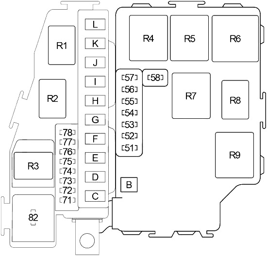
| Number | Amps [A] | Description |
|---|---|---|
| 51 | 10 | Air Conditioning Relay |
| 52 | 15 | Audio, satellite radio receiver, automatic CD changer, AV and Navi control unit, display, voice-activated control module |
| 53 | 20 | Engine control module (ECM) relay (ignition coils, condenser, intake valve control solenoid control valve) |
| 54 | 15 | Rear lamp relay (front/rear combination lamp, front/rear marker lamp, registration lamp, storage lamp, lighting control switch, ill: cigarette lighter, multifunction switch, VDC switch, emergency switch, audio module, automatic CD changer, A/T unit, clock, headlight aiming switch, AV and Navi control unit, air-conditioning seat switch, temperature-controlled seat level switch, ashtrays), LH/RH headlight adjustment motor, headlight battery saving control unit |
| 55 | 20 | Headlight (Low beam), Headlight Relay No. 1 |
| 56 | 15 | Horn relay, alternator |
| 57 | 20 | Left headlight (low beam), headlight relay #1 |
| 58 | 10 | Data link connector, EVAP canister purge volume control solenoid valve, EVAP canister vent control valve, vacuum shutoff valve bypass valve, variable intake air system (VIAS) control solenoid valve |
| 71 | 15 | Air Conditioning Controlled Seat Relay |
| 72 | 15 | Air-conditioning-controlled seat relay |
| 73 | 15 | Headlight (High beam), headlight relay 2, combination meter, daytime running light control unit |
| 74 | 15 | Throttle control motor relay |
| 75 | 20 | BOSE Speaker Amplifier |
| 76 | 15 | Front fog light relay |
| 77 | 10 | Intelligent Cruise Control (ICC) Unit |
| 78 | 10 | Safety Horn |
| 82 | 10 | Daylight Control Unit |
| B | 50 | Ignition relay (Fuses: “1”, “2”, “5”, “7”, “9”, “34”, “35”, “36”, “37”, “82”) |
| C | 50 | Accessory relay (Fuse: “4”; Fuse #3 – Cigarette lighter, front power socket), Fuse: “3”, “6”, “8”, “10”, “11”, “15”, ” 17″, “22” |
| D | – | – |
| E | – | – |
| F | 30 | VDC/TCS/ABS (solenoid valve relay) |
| G | 50 | Ignition switch |
| H | 40 | Circuit breaker #1 (electric window, door lock, driver’s door control unit, left rear door control unit, body control module (BCM), sunroof motor), circuit breaker #2 (electric window, door lock, passenger door control unit, right rear door control unit, driver’s seat control unit) |
| I | – | – |
| J | – | – |
| K | 50 | VDC/TCS/ABS (motorized relay) |
| L | 50 | Blower relay (Fuses: “31”, “33”), Fuse: “32” |
| R1 | Front Windshield Wiper | |
| R2 | Throttle control motor | |
| R3 | Lighthouse (#2) | |
| R4 | Lighthouse (#1) | |
| R5 | Park/neutral position | |
| R6 | Air Conditioning | |
| R7 | Tail lamp | |
| R8 | Horn | |
| R9 | Ignition | |