Infiniti FX50 (S51) (2008-2017) – fuse box diagram
Year of manufacture: 2008, 2009, 2009, 2010, 2011, 2012, 2013, 2014, 2015, 2016, 2017
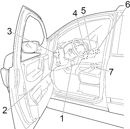
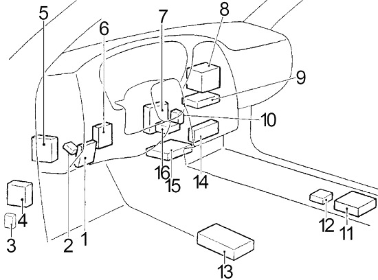
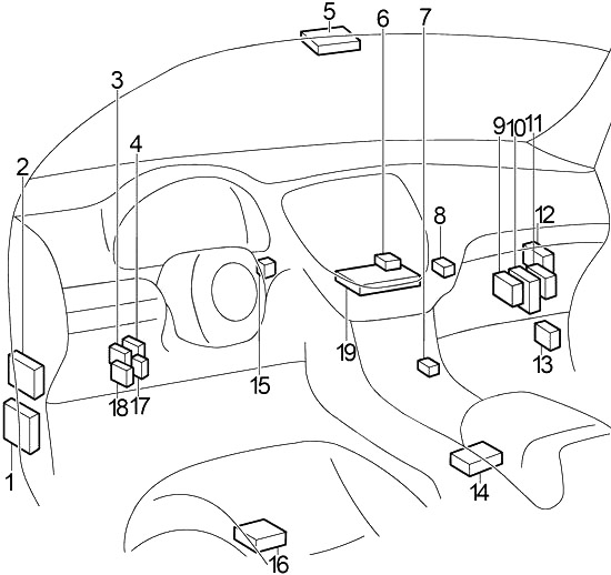
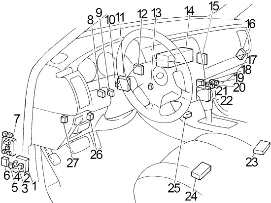
Instrument panel fuse panel (J/B)
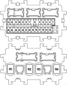
| No. | Amps [A] | Description |
| 1 | – | – |
| 2 | 10 | Passenger detection system control unit
Airbag diagnostic sensor unit |
| 3 | 10 | Front combination lamp , right;
Front combination lamp , left; Climate controlled ionizer; Seat Relay; Unified air conditioning meter and amplifier; Low tire pressure warning control unit; CAN port; AV control unit; Exhaust and external odor sensor; Automatic anti-glare interior mirror; ICC relay; ASCD Brake; Brake switch; Stop light switch; AFS control unit; Data link connector; Warning systems; Lane departure warning switch; Audible signal; Lane camera module; Tel adapter assembly. Heated seat relay; Heated seat switch (driver’s side); Heated seat switch (passenger side). |
| 4 | 10 | Combined counter backup lamp relay View around the monitor unit Sonar control unit |
| 5 | 20 | Accessory Relay |
| 6 | 10 | Key / socket Clock Data link connector Rain Sensor Intelligent warning key Buzzer Automatic anti-glare interior mirror |
| 7 | 10 | Body control module;
Stop light switch; ICC Brake Relay |
| 8 | 20 | Bose (audio system) |
| 9 | 10 | Ignition switch with push button in key slot |
| 10 | 10 | Body Control Module (BCM);
Automatic driving position controller; Control unit; Control unit full illumination; Memory Switch Seats; Driving seat control unit. |
| 11 | 10 | Counter on;
Unified meter and air conditioning amplifier; AWD control unit; CAN port; Pre-crash seat belt control unit (driver and passenger side). |
| 12 | – | Reservation |
| 13 | – | Reservation |
| 14 | – | – |
| 15 | 10 | Exterior mirrors |
| 16 | 20 | Rear window defogger |
| 17 | 20 | Rear window defogger |
| 18 | 10 | E-SUS control unit |
| 19 | – | – |
| 20 | 15 | Front power socket |
| 21 | 10 | Remote control switch for the side mirror;
Unified air conditioning meter and amplifier; Multifunction switch; Total lighting control unit; AV control unit (ambient); Monitor control unit; Adapter unit Tel; Satellite Tuner. |
| 22 | 20 | Console power socket;
Rear power socket. |
| 23 | 15 | Fan motor |
| 24 | 15 | Fan motor |
| 25 | – | Reservation |
| 26 | – | Reservation |
| Relay | ||
| R1 | Ignition Relay | |
| R2 | Rear windscreen defroster relay | |
| R3 | Accessory Relay | |
| R4 | Blower relay | |
Fuse box in engine compartment (IPDM E / R)
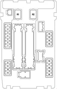
| No. | Amps [A] | Description |
| 1 | 15 | Fuel pump relay;
Fuel pump control module; Fuel level sensor assembly; Fuel pump; Engine control module (ECM). |
| 2 | 10 | Cooling fan relay 2 |
| 3 | 10 | Snow mode switch of the gearbox control module (MTC) |
| 4 | 10 | Fuel injector 1;
Injector No. 2; Injector No. 3; Injector No. 4; Injector No. 5; Injector No. 6; Injector #7 (VK engine); Injector #8 (VK engine); Engine Control Module (ECM); Body Control Module (BCM); Total lighting control unit. |
| 5 | 10 | ICC sensor Integrated unit;
Throttle pedal accelerator; ABS actuator and electrical unit (control unit); Steering angle sensor 1; Steering angle sensor 1; Side G sensor; AWD control unit; Power steering control unit; RAS control unit; ICC Warning; Brake control unit. |
| 6 | 15 | Heated oxygen sensor 2 (row 2);
Heated oxygen sensor 2 (row 1); Air/fuel ratio (A/F) Sensor 1 (row 1); Air/fuel ratio (A/F) Sensor 1 (row 2). |
| 7 | 10 | Combination Switch |
| 8 | – | – |
| 9 | 10 | A/C relay compressor |
| 10 | 15 | ECM relay;
Engine Control Module (ECM); Condenser; Time control solenoid valve; Intake valve; Time control solenoid valve (row 1); Intake valve timing control solenoid valve (row 2); Exhaust valve timing control solenoid valve (row 1); Exhaust valve regulation control solenoid valve (row 2); EVAP absorption vent control valve; Ignition coil 1 (with power transistor); Ignition coil #2 (with power transistor); Ignition coil #3 (with power transistor); Ignition coil 4 (with power transistor); Ignition coil #5 (with power transistor); Ignition coil #6 (with power transistor); Ignition coil #7 (with power transistor; VK engine); Ignition coil #8 (with power transistor; VK engine); EVAP canister purge volume control solenoid valve; Mass airflow sensor (row 2); Air mass flow sensor (row 1) ; VVEL control module. |
| 11 | 15 | Throttle control motor relay;
Engine control module (ECM). |
| 12 | 10 | Left front combination lamp (rear lamp);
Front right combination lamp (rear lamp). |
| 13 | 10 | Rear combination lamp, left;
Rear combination lamp, right; License plate lamp, left; License plate lamp, right; Glove box lamp; Full lighting control unit; Front power socket; ATT. changeover switch; AV control unit. |
| 14 | 10 | Front left (high beam) combination lamp |
| 15 | 10 | Front right combination lamp (high beam) |
| 16 | 15 | Left Headlight (Low beam) |
| 17 | 15 | Right Headlight (Low beam) |
| 18 | 10 | Front fog light relay
(Left front fog light, right front fog light) |
| 19 | – | – |
| 20 | 30 | Front Wiper Relay |
| Relay | ||
| R1 | – | |
| R2 | Start Control Relay | |
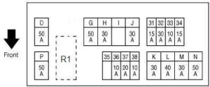
Engine compartment fuse box (E12)

| No. | Amps [A] | Description |
| 31 | 15 | Horn Relay 1;
Alternator. |
| 32 | 30 | Optional connector |
| 33 | 10 | AWD control unit;
Brake Assist Control Unit. |
| 34 | 15 | Front Exposure;
AV control unit (Overview); Monitor control unit; Subwoofer; Satellite radio tuner; Adapter Tel. |
| 35 | – | – |
| 36 | 10 | Transmission Control Module (TCM) |
| 37 | 20 | Motor relay RAS |
| 38 | 10 | Horn relay 2 |
| sun | 50 | Actuator VVEL motor relay |
| H. | 30 | Fuse block J / B IPDM E / R |
| I | – | – |
| jot | 30 | Pre-crash seat belt control unit (driver’s side) |
| K. | 30 | Pre-crash seat belt control unit (passenger side) |
| L | 40 | Body Control Module (BCM);
Automatic driving positioner Cont; Driver’s seat control unit; Lumbar support switch; Lateral support; Electric seat switch. |
| M | 30 | ABS actuator and electronic unit |
| N | 50 | ABS actuator and electronic unit |
| O | 50 | Cooling Fan Relay 1 |
| P. | 50 | Fuse block E213 – fuse #: Q (automatic tailgate control unit), 61 (accelerator pedal actuator), 62 (A/C controlled seat relay), 63 (A/C controlled seat relay, heated seat relay) |
| Relay | ||
| R1 | Horn relay 1 | |
Fuse block on the positive battery terminal
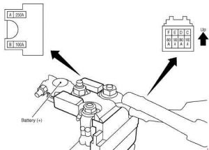
| No. | Amps [A] | Description |
| A | 250 | Starter alternator fuse no:
C. D, E |
| B | 100 | Fuse no:
O (cooling fan relay 1), S (cooling fan relay 2) |
| C | 100 | Fuse and Fuse Connection Block |
| D | 80 | Fuse block J / B (fuse numbers: 5, 6, 7, 8, 9, 10, 11)
For additional power supply from the ignition source |
| E | 100 | IPDM E / R (fuse no: 10, 11) for the ignition power source |
| F | 60 | IPDM E / R (fuse #: 18 (front fog light relay); high beam relay,
low headlight relay, rear lamp relay) to the ignition power source. |
Fuse box in engine compartment (E212; VK engine).
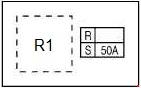
| No. | Amps [A] | Description |
| R | – | – |
| S | 50 | Cooling Fan Relay 2 |
| Relay | ||
| R1 | Cooling fan relay 2 | |
Engine compartment fuse box (E213)
| No. | Amps [A] | Description |
| 61 | 15 | Accelerator pedal actuator |
| 62 | 15 | Weather controlled seat relay |
| 63 | 10 | Weather controlled seat relay;
Heated seat relay. |
| Q | 30 | Automatic tailgate control unit |
| Relay | ||
| R6 | Horn relay 2 | |
| R8 | ICC Brake Holding Relay | |