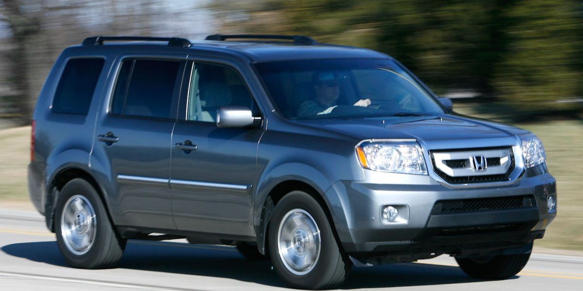
Honda Pilot (2009-2015) – Fuse box diagram
Year of manufacture: 2009, 2010, 2011, 2012, 2013, 2014, 2015.
Lighter fuse (power socket) in Honda Pilot (2009-2015). Is fuse 35 in the fuse box in the passenger compartment.
Passenger compartment


- Fuse box
- Meter control module
- Power Plug Relay Accessory Console #1
- 09-10: Rear Fan Motor Relay
- 11-15: Rear Fan Motor Relay
- Relay for console 2 power accessory socket
Passenger compartment fuse box


| No. | Amp [A] | Description |
| 1 | 7,5 | 4WD variable torque management system (VTM-4);
Control unit, VTM-4 relay. |
| 2 | 15 | 09-11:
Fuel pump (PGM-FI main relay #2); Immobilizer-keyless control unit; Powertrain control module (PCM). |
| 20 | ’12 -’15:
Fuel pump (PGM-FI main relay #2); Immobilizer-keyless control unit; Powertrain control module (PCM). |
|
| 3 | 10 | Alternator;
Electrical charge detector (ELD); Fuel vapor emission absorption valve (EVAP); Brake pedal position switch; Powertrain control module (PCM). |
| 4 | 7,5 | VSA modulator control unit;
Transverse acceleration sensor, longitudinal yaw rate. |
| 5 | 15 | ’09 -’11:
Front passenger seat heating pad (front passenger seat heating pad relay (high)); Front passenger seat heating pad (front passenger seat heating pad relay (low)); Driver’s seat heating pad (Driver’s seat heating pad relay (high)); Driver’s seat heating pad (Driver’s seat heating pad relay (low)). |
| 6 | – | – |
| 7 | 10 | Automatic lighting control unit;
Driver’s lumbar support motor; Driver’s lumbar support switch. |
| 8 | 7,5 | Automatic lighting control unit;
Parking and reversing control unit; Tire pressure monitoring system (TPMS) control unit. |
| 9 | 7,5 | Occupant Detection System (ODS) Unit;
Passenger airbag cut-off indicator; Supplemental Restraint System (SRS) assembly. |
| 10 | 7,5 | Motor assembly control relay (ACM) with active control;
Automatic dimming of the interior mirror; Rearview mirror; Electric compass assembly; Motor mount control assembly; Pressure gauge control module; Reverse the light to the left and to the right; Electric mirror control unit; Electric seat control unit; Electric tailgate control unit; Shift lock solenoid; Trailer lighting unit; 4WD variable torque management system (VTM-4); Seat heating control unit (’12 -’15); Control unit for automatic lighting (’12 -’15); Transmission range switch (’12 -’15); Navigation unit (’12 -’15). |
| 11 | 10 | Supplementary Restraint System (SRS) unit |
| 12 | 10 | Right headlight (driving lights) |
| 13 | 10 | Left Headlight (High beam) |
| 14 | 7,5 | Audio unit lighting;
Remote audio switch lighting; Audio-HVAC display illumination; Ambient lighting (console, glove box, roof); A/T transmission position indicator panel; Air conditioning module lamp or HVAC control unit lamp; Glove box lamp; Cruise control lighting; Console box illumination; Hazard warning light; Opening roof switch light; Multi-information switch light; Navigation control panel lights; Parking and reversing sensor switch light; Rear controller and screen light; Rear HVAC control; Panel lighting; Rear air conditioning control panel lighting; Illumination of the auxiliary RES socket assembly; Illumination of the seat heater switches; VSA switch light; VTM-4 interlocking switch light; Front passenger airbag cut-off indicator (’12 -’15); HFL navigation voice control, switch (’12 -’15); HFL switch (’12 -’15); Interior lighting switch; HomeLink switch. |
| 15 | 15 | ’09 -’10:
License plate illumination; Left front parking light; Front left marker light; Left rear marker light; Left taillights; Right front parking light; Right front side marker light; Right rear right side marker light; Right rear lights; Trailer Light Relay. |
| 10 | ’11 -’15:
License plate illumination; Left front parking light; Front left marker light; Left rear marker light; Left taillights; Right front parking light; Right front side marker light; Right rear right side marker light; Right rear lights; Trailer Light Relay. |
|
| 16 | 15 | Right Headlight (Passing Beam) |
| 17 | 15 | Left Headlight (Low beam) |
| 18 | 20 | Daytime Running Lights;
Multiplex Integrated Control Unit (MICU). |
| 19 | 15 | Small headlights;
Multiplex Integrated Control Unit (MICU); Fuses (passenger compartment fuse box): Nos. 14, 15. |
| 20 | 7,5 | Control unit of the tire pressure monitoring system (TPMS) |
| 21 | 20 | Reflector (main BH / LLO);
Multiplex Integrated Control Unit (MICU). |
| 22 | 7,5 | Powertrain Control Module – PCM (VBSOL2) |
| 23 | 7,5 | Starter (STRLD);
Powertrain control module (PCM). |
| 24 | – | – |
| 25 | – | – |
| 26 | 20 | Driver front window switch;
Windshield master switch (’09 -’11); Multiplex door control unit (’12 -’15). |
| 27 | 20 | Optional connector |
| 28 | 20 | Control unit, sliding roof motor |
| 29 | 20 | Electric door lock;
Multiplex Integrated Control Unit (MICU). |
| 30 | 20 | Passenger windshield switch |
| 31 | 30 | Sound Amplifier |
| 32 | 20 | Right rear window switch |
| 33 | 20 | Rear left window switch |
| 34 | – | – |
| 35 | 10 | Audio module;
Relay for the accessory power socket in the trunk; Relay for accessory power socket on console 1 and 2; Relay for front accessory power socket; Hands-free (trip) connection control unit; HFL microphone; Navigation; ANC; Key lock solenoid; Integrated multiplex (MICU); Navigation display; Audio navigation unit; Audio-USB adapter control unit; Rear noise-canceling active microphone; Noise-canceling active front microphone; HandsfreeLink control unit; Interface marking. |
| 36 | 10 | AC inverter unit;
A/C compressor clutch relay; Automatic dimming of interior mirror, rear view mirror; Audio-HVAC Screen; Air conditioning unit or HVAC control unit; Driver’s seat heating relays; Fan control relay (diode); Front fan motor relay; Front passenger seat heater relays; Left and right mirror actuators; Mirror power switch; Second row left seat heating relays; Optional connector; Windshield master switch (’09 -’11); Electric mirror control unit, Radiator fan relay (diode), Relays for the heating of the second row right-hand seats; Relay for the rear blower motor; Rear air conditioning control panel or rear HVAC control panel; Rear window de-icer relay; Rear mode control motor; IG2 trailer relay; Multiplex door control unit (’12 -’15). |
| 37 | 7,5 | Daytime Running Lights;
Multiplex Integrated Control Unit (MICU). |
| 38 | 30 | Windshield wiper motor;
Rear windshield washer motor; Windshield washer motor; Multiplex Integrated Control Unit (MICU). |
| Fuse Holder | ||
| – | 7,5 | Starter switch, ignition switch (ST);
Remote engine start connector; Powertrain Control Module (PCM). |
| Relay | ||
| R1 | – | Window Actuator |
| R2 | – | Fuel pump (PGM-FI Main 2) |
| R3 | – | Notch initial 1 |


- ’11 -’15: Glass hatch
- ’09 -’10: Sewer glass hatch
- Parking and Sensor Reversing Control Unit
- Automatic Lighting Control Unit
- Relay for 4WD variable torque management system (VTM-4)
- Front Accessory Power Plug Relay
- Navigation Screen Audio-HVAC Screen
- Engine Mount Control Unit
- High beam relay
- Light Fog Relay
- Relay for accessory power socket in the trunk
- Audio unit
- Air conditioning control unit HVAC control unit
- Navigation Panel
- Ignition Relay (Acc Cut)
- Ignition Relay (IG2)
- Start Relay 2


- Immobiliser-Keyless
- USB Adapter
- Supplementary Restraint System (SRS) Unit
- Sound Amplifier
- AC inverter unit
- HandsFreeLink control unit
Engine compartment


- Powertrain control module (PCM)
- Fuse box 1
- VSA modulator control unit
- Fuse box 2
Engine compartment fuse box #1


| No. | Amp [A] | Description |
| 1 | 120 | Battery;
Power Distribution. |
| – | – | |
| 2 | 50 | Ignition switch (BAT);
Starter solenoid (starter relay 1 and 2); Fuse (passenger compartment fuse box): NO. 23. |
| 80 | Fuses (passenger compartment fuse box):
Nos. 5, 6, 7, 27, 28, 29, 31. |
|
| 3 | 30 | 12-15:
AC inverter unit. |
| 40 | 12-15:
Front blower motor (front blower motor relay) |
|
| 4 | 50 | Fuses (passenger compartment fuse box):
Nos. 18, 19, 20, 21. |
| 40 | Window elevator relay, b
Fuses (passenger compartment fuse box): NOS. 24, 25, 26, 30, 32, 33. |
|
| 5 | – | – |
| 6 | 30 | A/C condenser fan motor
(A/C condenser fan relay) |
| 7 | 30 | Radiator fan motor
(radiator fan relay) |
| 8 | 30 | Rear window defogger
(rear window defogger relay) |
| 9 | 40 | 09-11:
Front Fan Motor (front fan motor relay) |
| 10 | 20 | Fog light relay;
Fog lights. |
| 11 | 15 | PGM-FI Subtransmitter;
Front (A / F) fuel/air ratio sensor; Front secondary heated oxygen (HO2S) sensor; Rear fuel/air ratio sensor (A / F); Rear auxiliary heated oxygen (HO2S) sensor; Evaporative emission control (EVAP); Canister vent shut-off valve (’12 -’15); Fuse (engine compartment fuse box): NO. 15. |
| 12 | 10 | Engine mount control unit
(Active control motor mount (ACM) control relay) |
| 13 | 20 | Front passenger seat reclining engine
(electrically adjustable passenger seat adjustment switch) |
| 14 | 20 | Front passenger seat displacement motor
(electrically adjustable passenger seat adjustment switch) |
| 15 | 7,5 | A/C condenser fan relay (diode) |
| 16 | 20 | 09-11:
High beam relay, headlights (high beam headlights) |
| 7,5 | 12-15:
Powertrain Control Module – PCM (VBUM) |
|
| 17 | 20 | Audio Unit,
HFL; Navigation; ANC Microphone. |
| 18 | 15 | Ignition coil relay;
Ignition coils. |
| 19 | 15 | PGM-FI main relay #1;
Crankshaft position sensor (CKP); Camshaft position sensor (CMP); Electronic throttle control system (ETCS) control relay; Injectors; Mass air flow (MAF) sensor; Powertrain control module – PCM; PGM -FI main relay 2 (fuel pump). |
| 20 | 7,5 | A/C compressor clutch
(A/C Compressor Clutch) |
| 21 | 15 | Electronic Accelerator Control System (ETCS) control relay |
| 22 | 10 | 09-11:
Baggage area lighting; Driver’s door interior lighting; Cosmetic driver lighting with mirror; Individual front map lights; Front passenger door interior lighting; HomeLink unit; Ignition key illumination; Interior illumination of the tailgate switch; Left rear outer rear door switch light; Passenger lighting; Mirrored cosmetic lighting; Individual map backlights (second); Individual map backlights (third); Interior lighting for the right rear door; Optional connector (Illumination of the running board on the left and right running board lighting). |
| 7,5 | 12-15:
Loading zone lighting; Illumination at the driver’s door; Cosmetic driver lighting with mirror; Individual front map lights; Interior passenger front door illumination; HomeLink module; Ignition Bulb; Interior tailgate switch light; Passenger side mirror illumination; Individual map rear lights (second); Individual map backlights (third); Optional connector (automatic dimming of the interior mirror); Optional connector (left running board light and Right running board light). |
|
| 23 | 10 | Audio-HVAC display, with
Data link connection (DLC), m indicator control unit, j HandsFreeLink control unit, j Mirror control unit, j control unit for electrically adjustable seat, j ed control unit for electrically operated tailgate, w main window switch (’09 -’11), s rear view and screen, w navigation display, m active noise reduction module (’12 -’15), p HFL-ANC front microphone (’12 -’15), p HFL-navigation-ANC front microphone (’12 -’15); mmobiliser-Keyless control unit (’12 -’15); Multiplex Gate Control Unit (’12 -’15); Audio-USB Adapter Control Unit (’12 -’15). |
| Relay | ||
| R1 | – | Fan control |
| R2 | – | Active motor mount control (ACM) |
| R3 | – | PGM-FI Sub |
| R4 | – | Ignition Coil |
| R5 | – | A/C condenser fan |
| R6 | – | Front fan motor |
| R7 | – | Ear defogger glass |
| R8 | – | A/C compressor clutch |
| R9 | – | Radiator Fan |
| R10 | – | Electronic Accelerator Control System (ETCS) |
| R11 | – | PGM-FI main number 1 |
Engine compartment fuse box 2


| No. | Amp [A] | Description |
| 1 | 40 | Electric tailgate control unit |
| 2 | 20 | 4WD Variable Torque Management System (VTM-4)
Control unit, relay VTM-4 |
| 3 | 30 | Fuses (luggage compartment fuse box):
Nos. 1, 2, 3, 4 |
| 4 | 40 | VSA modulator control unit |
| 5 | 30 | Rear fan motor relay |
| 6 | 30 | VSA modulator control unit |
| 7 | 15 | Direction indicators / warning lights;
Multiplex Integrated Control Unit (MICU). |
| 8 | 20 | Tailgate control unit (closest to the engine) |
| 9 | 20 | Control unit for electrically adjustable seat;
Motor for electrically lowered rear seat; Adjustment switch for electrically adjustable driver’s seat; Electrically adjustable reclining seat motor. |
| 10 | 20 | Control unit for electrically adjustable seat;
Electrically adjustable seat motor; Adjustment switch for electrically adjustable driver’s seat; Motor for electrically raised front seat. |
| 11 | 20 | Brake pedal position switch;
Upper brake light; Left and right brake light; Multiplex Integrated Control Unit (MICU); Powertrain Control Module (PCM); Electric trailer brake connector; Towing unit. |
| 12 | 15 | Console 2 accessory power socket
(Rear console accessory power socket relay #2) |
| 13 | 10 | Rear wiper motor;
Rear wiper motor relay 1 (forward); Rear wiper motor relay 2 (backward). |
| 14 | Electric trailer brake connector | |
| 15 | 20 | AC inverter unit;
Seat heating control unit (’12 -’15). |
| 16 | 15 | Console 1 accessory power socket
(Rear console power socket relay accessory No. 1) |
| 17 | 20 | Trailer Lighting Connector
(trailer relay IG2) |
| 18 | 15 | Front accessory power socket
(front accessory power socket relay) |
| 19 | 15 | Power socket for accessories in the luggage compartment
(relay for accessory power socket in the trunk) |
| 20 | 20 | Hatch window opening actuator, hatch window relay |
| 21 | 15 | Second row left seat heating pad
(left second row seat heater relay (high)), l Left second row seat heater relay (left row seat heating relay (bottom)), p Second row right seat heating pad (Right second row seat heating pad relay) (High)), Right second row seat heating pad (Second row right (bottom) seat heating relay). |
| 22 | – | – |
| Relay | ||
| R1 | – | Rear wiper motor 1 (forward) |
| R2 | – | Rear wiper motor 2 (rear) |
Luggage compartment


- Electric tailgate control unit
- Electric Compass
- Electric tailgate drive
- Trailer lighting control unit
- 4WD Variable Torque Management System (VTM-4) Control Unit
- Fuse Box
Luggage compartment fuse box


| No. | Amp [A] | Description |
| 1 | 7.5 | Trailer Lighting Control Unit |
| 2 | 7.5 | Trailer Lighting Control Unit |
| 3 | – | – |
| 4 | 20 | Trailer Lighting Connector
(trailer lighting relay) |
| Relay | ||
| R1 | – | IG2 trailer |
| R2 | – | Trailer Lighting |


- Rear controller and display
- Sunroof control unit / motor
- Xm Receiver

