Fuse diagrams and relay boxes – Honda Passport
Applies to vehicles manufactured over the years:
1998, 1999, 2000, 2001, 2002.
Passenger compartment fuse box
The fuse block is located behind the cover on the left side of the instrument panel.
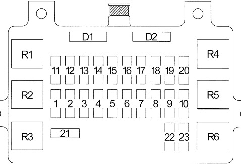
| Number | Amps [A] | Description |
|---|---|---|
| 1 | 20 | Accessory power sockets |
| 2 | 15 | Clock, stereo sound system |
| 3 | 10 | Starting system |
| 4 | 15 | Tail light relay (A/T transmission position indicator, alarm and relay controls, dash and console lights, fuel injection system, headlight switch, headlight reminder, multiplex control system, parking light, tail light, registration light, door lock/keyless entry/security system, trailer light connector) |
| 5 | 10 | Alarm control and relay, starter light, ceiling light, dome light (2001), ignition key reminder (LX), map light |
| 6 | 15 | ABS, automatic transmission control, brake lights, cruise control, locking system, trailer light connector |
| 7 | 20 | Ignition key reminder (EX), electric door locks/keyless access/security system |
| 8 | 10 | Defogger Mirrors |
| 9 | 15 | Rear window defogger |
| 10 | 15 | Rear window defogger |
| 11 | 15 | ABS, indicators, indicators, locking system, multiplex control system |
| 12 | 15 | Automatic transmission control, fuel injection system, starting system |
| 13 | 15 | Ignition System |
| 14 | 15 | Automatic transmission control, reversing lights, cruise control, map light clock (2001), multiplex control system, gear shift system (2001-2002), transmission range switch |
| 15 | 15 | Alarm and relay control unit, fan control, moonroof, power windows, flight shift system (2000), trailer light connector, turn signals |
| 16 | 10 | Alarm and relay control unit, rear window and mirror demisters, rear wiper/washer |
| 17 | 20 | Alarm and relay control unit, windshield wiper/washer |
| 18 | 10 | Mirrors, stereo sound system |
| 19 | 15 | Accessories for electrical outlets, cigarette lighter |
| 20 | 10 | Security and keyless access system |
| 21 | 30 | Electric moonroof, Adjustable seat (2001-2002), Electric windows |
| 22 | 10 | SRS |
| 23 | – | – |
| R1 | Tail lights | |
| R2 | – | |
| R3 | Accessory power socket | |
| R4 | Supply of windows | |
| R5 | 2001: Light from the Dome | |
| R6 | Rear window defogger | |
| D1 | Ceiling lights, keyless entry and security system | |
| D2 | Keyless access and security system | |
Fuse box in engine compartment
Located on the right side of the engine compartment.
Diagram (Type 1)
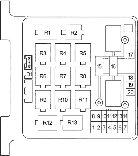
| Number | Amps [A] | Description |
|---|---|---|
| 1 | 15 | Emergency lights, trailer light connector |
| 2 | 10 | Alarm and relay control unit, data link connector (DLC), safety horn |
| 3 | 10 | Alternator |
| 4 | – | – |
| 5 | 15 | Blower Control |
| 6 | 15 | Blower Control |
| 7 | 10 | Air Supply |
| 8 | 10 | Left-Wing Headlights, Fog Lights |
| 9 | 10 | Headlight right |
| 10 | 15 | Fog Lights |
| 11 | 20 | Heated oxygen sensors |
| 12 | 20 | Fuel Pump |
| 13 | 15 | Automatic transmission control, fuel injection system, indicators |
| 14 | Daytime Running Lights | |
| 15 | 60 | Fuel injection system, power distribution (BAT) |
| 16 | 100 | A/C compressor control, fan control, charging system, fog lights, power distribution (BAT), starting system |
| 17 | 30 | Motor control module |
| 18 | 50 | ABS |
| 19 | 50 | Power Distribution (BAT) |
| 20 | 30 | Condenser Fan |
| R1 | Fuel Pump | |
| R2 | – | |
| R3 | Headlight | |
| R4 | Starter | |
| R5 | Condenser Fan | |
| R6 | – | |
| R7 | – | |
| R8 | Air Conditioning | |
| R9 | Engine Control Module (ECM) (M/T) | |
| Powertrain Control Module (PCM) (A/T) | ||
| R10 | – | |
| R11 | Fog lamps | |
| R12 | A/C Heater | |
| R13 | A/C Compressor | |
| D1 | Brake system indicator light | |
Diagram (Type 2)
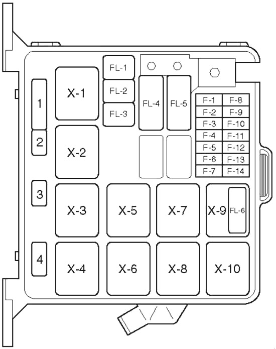
| Number | Amps [A] | Description |
|---|---|---|
| F1 | 15 | Hazard Warning Light |
| F2 | 10 | Alarm and relay control unit, horn, anti-theft horn |
| F4 | 20 | Blower motor, blower heater |
| F5 | 10 | A/C thermostatic relay, electronic thermostat, A/C compressor relay, magnetic clutch |
| F8 | 10 | Headlight – left, high beam indicator, fog light relay |
| F9 | 10 | Lighthouse – on the right |
| F10 | 15 | Fog Lights |
| F11 | 20 | Oxygen sensor |
| F12 | 20 | Fuel Pump |
| F13 | 15 | Motor control module |
| F14 | – | – |
| FL1 | 60 | EHCU |
| FL2 | 30 | Condenser Fan |
| FL4 | 100 | Ignition switch, starter relay, air conditioning, generator, heating relay, Fuse: F10, FL1, FL2, FL5, FL6 |
| FL5 | 60 | Ignition switch, fuel pump relay, engine control module relay, drive train module |
| FL6 | – | – |
| X1 | Headlight | |
| X2 | Fog lamps | |
| X3 | Starter | |
| X4 | A/C Compressor | |
| X5 | Thermo | |
| X6 | Heater | |
| X7 | Fuel Pump | |
| X8 | Motor control module | |
| X9 | 6VD1: Condenser fan | |
| X10 | – | |
| 1 | Brake | |
| 2 | – | |
| 3 | – | |
| 4 | – | |