Fuse and relay box diagrams – Honda Fit GD
Applies to vehicles manufactured over the years:
2006, 2007, 2008.
The cigarette lighter (power outlets) is responsible for. Fuse #27 in the instrument panel fuse box.
Passenger compartment
- Fuse box
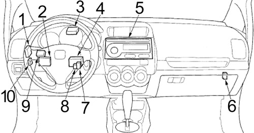
- Safety control unit
- Electronic Power Steering Control Unit (EPS)
- Control unit for tire pressure monitoring system (TPMS)
- Control unit for daytime running lights
- Audio unit
- Throttle actuator control module
- Beam cut-off relay
- Daytime Running Light Relay
- Imoes Unit
- Single Keyless Input Receiver
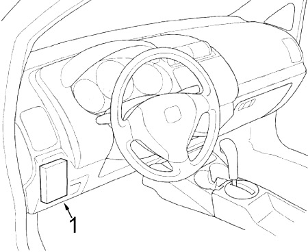
Instrument Panel Fuse Box Diagram
The internal fuse box is located behind the catches, as shown. driver’s coin tray. To access, remove the tray by turning the knob counterclockwise and then pulling it toward you. To install the coin tray, align the tabs at the bottom, rotate the tray upward to engage with the side clips, then turn the knob clockwise.
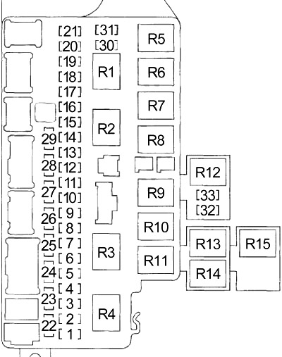
| Number | Amps [A] | Description |
|---|---|---|
| 1 | 10 | Emergency lights, A/T reversing relay |
| 2 | – | – |
| 3 | 10 | Indicator control module, keyless entry receiver module, safety control module, electronic power steering (EPS) control module, Imoes module, tire pressure monitoring control module (TPMS) |
| 4 | 10 | Indicator control module (indicator/danger circuit) |
| 5 | – | – |
| 6 | 30 | Windshield wiper motor, windshield washer motor, rear window washer motor |
| 7 | 10 | Occupant Detection System (ODS) unit, Supplementary Restraint System (SRS) unit |
| 8 | 7,5 | Daytime running light control unit |
| 9 | 20 | Rear window defogger |
| 10 | 7,5 | Left mirror, right mirror, rear window defroster switch indicator light, rear window defroster relay, radiator fan motor relay, air conditioner compressor relay, air conditioner condenser fan relay |
| 11 | 15 | ECM/PCM, immobilizer-receiver control unit, fuel pump |
| 12 | 10 | Windshield relay, windshield main switch, rear wiper motor |
| 13 | 10 | Supplementary Restraint System (SRS) Unit |
| 14 | 15 | PGM-FI Main Relay 1, PGM-FI Main Relay 2, ECM/PCM |
| 15 | 20 | Rear left window motor |
| 16 | 20 | Right rear window motor |
| 17 | 20 | Passenger windshield motor |
| 18 | 10 | Daytime running light control unit |
| 7,5 | Control unit for tire pressure monitoring system (TPMS) | |
| 19 | – | – |
| 20 | – | – |
| 21 | 20 | Fog Lights |
| 22 | 10 | Rear light relay, illumination lights, marker/left rear light, marker/right rear light, marker/left rear light, marker/right rear light, marker/left rear light, marker/left rear light, marker/right rear light |
| 23 | 10 | Air/fuel ratio (A/F) sensor, evaporative emission control canister vent valve (EVAP) |
| 24 | – | – |
| 25 | 7,5 | ABS modulator control unit |
| 26 | 7,5 | Audio unit, indicator control module, key lock solenoid |
| 27 | 15 | Accessory power socket |
| 28 | 20 | Driver door lock actuator, front passenger door lock actuator, left rear door lock actuator, right rear door lock actuator, rear door lock actuator |
| 29 | 20 | Driver window motor, electric window main switch |
| 30 | – | – |
| 31 | 7,5 | Fuel/air ratio sensor relay (A/F) |
| 32 | 15 | Throttle actuator control module |
| 33 | 15 | Ignition Coil Relay |
| R1 | Initial cut | |
| R2 | Supply of windows | |
| R3 | Fan motor | |
| R4 | A/T Inverter | |
| R5 | Door Lock | |
| R6 | Driver’s door unlocking | |
| R7 | Unlocking the passenger door and unlocking the tailgate | |
| R8 | Tail lights | |
| R9 | Ignition Coil | |
| R10 | PGM-FI Main №2 (Fuel Pump) | |
| R11 | PGM-FI Main №1 | |
| R12 | Throttle actuator control module | |
| R13 | Rear window defogger | |
| R14 | Air/Fuel Ratio Sensor (A/F) | |
| R15 | Fog lamps | |
Engine compartment
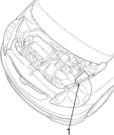
- Fuse box
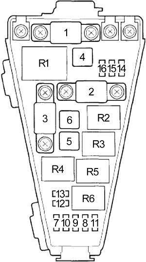
Diagram of the fuse box in the engine compartment
The main fuse box under the engine cover is located in the engine compartment on the driver’s side. To open it, press the tabs as shown. The secondary fuse box is located on the positive terminal of the battery.
| Number | Amps [A] | Description |
|---|---|---|
| 1 | 80 | Battery, power distribution |
| 2 | 60 | Electronic Power Steering (EPS) |
| 3 | 50 | Ignition switch |
| 4 | 30 | ABS modulator control unit |
| 5 | 40 | Fan motor |
| 6 | 40 | Fuses: № 14, 15, 16, 17, 28, 29 |
| 7 | 30 | Fuses: № 18, 21 |
| 8 | 10 | Keyless entry receiver unit, Indicator control unit, Security control unit, Immobilizer-receiver control unit, Audio unit, Imoes unit |
| 9 | 30 | Fuses: № 22, 23 |
| 10 | 30 | Radiator fan motor |
| 11 | 30 | A/C condenser fan motor, A/C compressor clutch |
| 12 | 20 | Right Headlight |
| 13 | 20 | Left headlight, high beam indicator |
| 14 | 10 | Indicator control module (indicator/danger circuit) |
| 15 | 30 | ABS modulator control unit |
| 16 | 15 | Relay horn, horn, ECM/PCM, brake lights, high mounted brake light |
| R1 | Electrical charge detector (ELD) | |
| R2 | Radiator Fan | |
| R3 | Horn | |
| R4 | Headlight | |
| R5 | A/C condenser fan | |
| R6 | A/C compressor clutch | |
| – | 80A | Battery |