
Fuse diagrams and relay boxes – Ford Expedition U324
Applies to vehicles manufactured over the years:
2015, 2016, 2017.
Diagram of the fuse box in the passenger compartment
The fuse panel is located under the right side of the instrument panel. Pull the panel toward you, tilt it away from the side, and remove the panel to access the fuse box. To reinstall it, snap the tabs into the slots in the panel and then press it down.
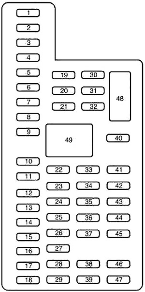
| Number | Amps [A] | Description |
|---|---|---|
| 1 | 30 | Driver’s window |
| 2 | 15 | Rear seat control . |
| Multimedia door module | ||
| 3 | 30 | Passenger window |
| 4 | 10 | Search lamps |
| 5 | 20 | Amplifier |
| 6 | 5 | Rear automatic electronic temperature control |
| 7 | 7,5 | Mirror supply |
| Driver’s seat memory switch | ||
| 8 | – | Not used |
| 9 | 10 | SYNC |
| liftgate, | ||
| Electrical cladding panel, | ||
| Show | ||
| 10 | 10 | Activate accessory relay |
| 11 | 10 | Passive input/startup module |
| 12 | 15 | Interior lighting, |
| Puddle Lamps | ||
| 13 | 15 | Right and stop/steer indicators |
| 14 | 15 | Left and Stop/Direction Indicators |
| 15 | 15 | Reversing lamp, |
| Center high stop light, | ||
| CE Mirror | ||
| 16 | 10 | Right front dipped beam |
| 17 | 10 | Front left dip beam |
| 18 | 10 | Brake derailleur lock/ LED start button/ keypad illumination, |
| Electric folding seat in the third row , | ||
| Passive entry chime start | ||
| 19 | – | Not used |
| 20 | 20 | Interlocking/Unlocking Relays |
| 21 | – | Not used |
| 22 | 20 | Horn |
| 23 | 15 | Steering wheel control module, |
| Group | ||
| 24 | 15 | Adjustable pedals/column with power adjustment, |
| Data Connections | ||
| 25 | 15 | tilt tab release, |
| Lift gate window opening motor | ||
| 26 | 5 | Press to activate the switch |
| 27 | 20 | Passive input/startup module |
| 28 | 15 | Ignition, |
| Key lock switch | ||
| 29 | 20 | Radio, |
| GPS | ||
| 30 | 15 | Front parking lights |
| 31 | 5 | Trailer brake on/off |
| 32 | 15 | Supply ventilation, |
| Driver window motor, | ||
| Inverter. | ||
| 33 | 10 | CCD Suspension Module |
| 34 | 10 | Rear parking assistance, |
| Rear camera, | ||
| BUS | ||
| Heated seat | ||
| 35 | 5 | Climate module, |
| O/D switch | ||
| 36 | – | Not used |
| 37 | 10 | 4X4 Module |
| 38 | 10 | CE Mirror, |
| Opening Ceiling | ||
| CD/DVD, | ||
| AM/FM Radio | ||
| 39 | 15 | Front left and right driving lights |
| 40 | 10 | Parking/rear lights |
| 41 | 7,5 | Gearbox module |
| 42 | – | Not used |
| 43 | – | Not used |
| 44 | – | Not used |
| 45 | 5 | not used (reserve) |
| 46 | 10 | Climate control |
| 47 | 15 | Fog Lights |
| 48 | 30 | Front passenger and rear window switch |
| 49 | – | Window and Fan Relay |
Diagram of the fuse box in the engine compartment
The power distribution box is located in the engine compartment.
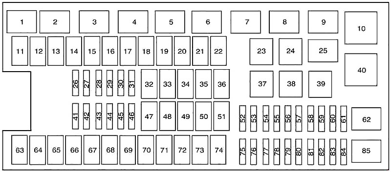
| Number | Amps [A] | Description |
|---|---|---|
| 1 | – | Rear windscreen washer relay |
| 2 | – | Startup Relay |
| 3 | – | Blower motor relay |
| 4 | – | Rear wiper relay |
| 5 | – | Fuel Pump Relay |
| 6 | – | Electronic cooling fan |
| 7 | – | Heated rear window/view mirror defroster |
| 8 | – | Electronic cooling fan |
| 9 | – | Start/start relay |
| 10 | – | Control box relay. |
| 11 | 40 | Strong running boards |
| Heated seats | ||
| 12 | 40 | Start/stop, relay |
| 13 | 30 | Startup Relay |
| 14 | 50 | Electronic cooling fan |
| 15 | – | Not used |
| 16 | 50 | Electronic Fan |
| 17 | – | Not used |
| 18 | 30 | Trailer Brake |
| 19 | 20 | Power point (console) |
| 20 | 20 | Module 4×4 HAT 2 |
| 21 | 30 | Towing Module |
| 22 | 30 | Electric passenger seat |
| 23 | – | Air Conditioning Clutch Relay |
| 24 | – | Trailer parking light relay |
| 25 | – | Not used |
| 26 | 10 | ALT sensor |
| 27 | 20 | Module 4×4 HAT 1 |
| 28 | 25 | Trailer parking light relay |
| 29 | 10 | Integrated wheel end solenoid valve |
| 30 | 10 | Air Conditioning Clutch Relay |
| 31 | 15 | Spare bulb for towing a trailer |
| 32 | 40 | Blower motor relay |
| 33 | 40 | 110 V AC Supply Point |
| 34 | 30 | Auxiliary fan motor |
| 35 | 30 | Traction train control module relay |
| 36 | 30 | Electric lift door |
| 37 | – | Not used |
| 38 | – | Not used |
| 39 | – | Trailer Trailer Hazard Light Relay |
| 40 | – | Electronic Fan Relay 2 |
| 41 | 10 | Drive train control module maintains power |
| 42 | 5 | Start/start relay |
| 43 | 10 | Brake on/off switch |
| 44 | 20 | Fuel pump relay |
| 45 | 10 | Not used (reserve) |
| 46 | 15 | Windshield washer pump front/rear |
| 47 | 30 | Rear wiper motor |
| 48 | 40 | Towing Module |
| 49 | – | Not used |
| 50 | 30 | Front wiper motor relay |
| 51 | 40 | Heated rear window/view mirror defroster |
| 52 | 10 | Anti-lock braking system during startup/startup |
| 53 | 5 | ISP traction unit control module |
| 54 | 5 | Power steering |
| 55 | – | Not used |
| 56 | 30 | Passenger compartment fuse panel Power supply R/S |
| 57 | 5 | Fan motor operation/startup |
| 58 | – | Not used |
| 59 | 15 | Heated mirrors |
| 60 | – | Not used |
| 61 | – | Not used |
| 62 | – | Not used |
| 63 | 25 | Electronic Fan |
| 64 | 30 | Opening roof |
| 65 | 20 | Not used (reserve) |
| 66 | 20 | Auxiliary power point (rear of center console) |
| 67 | 40 | Air-conditioned front row seats |
| 68 | 30 | Antilock brake system valves |
| 69 | 60 | Pump Anti-lock Braking System |
| 70 | 30 | Electric folding seat in the third row |
| 71 | 20 | Auxiliary power point/torque |
| 72 | 20 | Auxiliary power point (right rear quarter panel) |
| 73 | 20 | Rear seat air conditioning module |
| 74 | 30 | Electrically adjustable driver’s seat |
| 75 | 25 | Vehicle power 1 – power unit control module |
| 76 | 20 | Vehicle power 2 – power unit control module |
| 77 | 20 | Vehicle power 4 – ignition coils |
| 78 | – | Not used |
| 79 | 15 | Vehicle power 3 – power unit control module |
| 80 | – | Not used |
| 81 | – | Not used |
| 82 | 5 | Rain Sensor |
| 83 | – | Not used |
| 84 | – | Not used |
| 85 | – | Wiper Motor Relay |


