Fuse diagram and relay box – Dodge Dart
Applies to vehicles new in years:
2013.
Internal fuse box
Located on the driver’s side under the instrument panel.
There are also fuses in the BCM module, which is located behind the left side of the instrument panel.
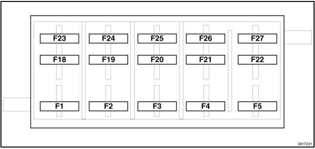
| Recess | Amps [A]/coloring | Description |
|---|---|---|
| F1 | 20 A yellow | Heated front seats |
| F2 | 20 A yellow | Heated rear seats, heated steering wheel |
| F3 | 10 A red | PAM, rear camera, LBSS, RBSS, compass |
| F4 | 15 A blue | IPC |
| F5 | 10 A red | HVAC, humidity sensor, car temperature sensor, interior mirror mount |
| F18 | 15 A blue | Radio |
| F19 | 10 A red | Fuel Door |
| F20 | 10 A red | SCCM, SAS, change bench |
| F21 | 10 A red | Diagnostic port |
| F22 | 10 A red | UGDO, MOE |
| F23 | 20 A yellow | Opening roof |
| F24 | 5 A Tan | Direct battery for PDC under the engine compartment cover (RLY coils) |
| F25 | 5 A Tan | DDCT Channel 4 |
| F26 | 5 A Tan | Stop lamp switch |
| F27 | 10 A red | Pneumatic lumbar support (solenoid valve), pneumatic lumbar support (pump motor) |
Motor compartment
The power distribution center (PDC) is located on the right side of the engine compartment, near the battery.
In addition, there are several fuses on the battery terminal.
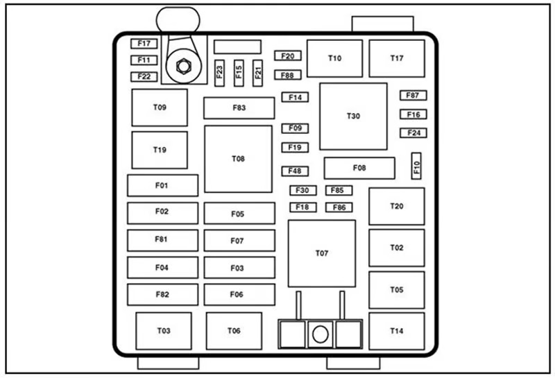
| Depression | Maximum fuse | Mini fuse | Description |
|---|---|---|---|
| F01 | 70 Amp Tan | – | Direct supply of battery #1 to BCM |
| F02 | 60 Amp blue | – | Direct supply of battery #2 to BCM |
| F03 | 30 A green | – | Output for start relay #1 |
| F04 | 40 A orange | – | ESP pump motor |
| F05 | 40 A orange | – | DDCT Channel 1 (SDU) |
| F06 | 30 A green | – | Direct supply of battery #3 to BCM |
| F07 | 40 A orange | EBL RLY coil, motorized blower coil RLY | |
| F09 | 5 A Tan | Radiator fan on RLY coil, Radiator fan on RLY coil | |
| F10 | – | 10 A red | ORC |
| F11 | – | 20 A yellow | ECM, EPS, lamp reversal switch |
| F14 | – | 15 A blue | DDCT channel #2 |
| F15 | – | 15 A blue | DDCT Channel No. 3 |
| F 16 | – | 15 A blue | Ignition coils, coil capacitor |
| F17 | – | 15 A blue | ESC, brake pedal switch, CMO |
| F18 | – | 20 A yellow | ECM |
| F19 | – | 10 A red | A/C compressor clutch |
| F20 | – | 30 A green | EBL |
| F21 | – | 20 A yellow | Fuel Pump |
| F22 | – | 10 A red | ORC |
| F23 | – | 25 Amp Natural | “ESC” |
| F24 | 20 A yellow | ECM, fuel injectors, active grille shutter (AGS) | |
| F30 | – | 20 A yellow | Power socket (console) |
| F81 | 60 Amp blue | Internal PDC battery power, electric seats | |
| F82 | 30 A green | – | Amplifier |
| F83 | 40 A orange | – | HVAC fan motor |
| F84 | – | 20 A yellow | Lighter |
| F85 | 10 A red | Sunroof, LRSM, socket (console), UCI/ AUX door, cigarette lighter | |
| F86 | – | 20 A yellow | – |
| F87 | 10 A red | Sluice, purge solenoid valve, OBD purge valve, lambda probe heaters | |
| F88 | – | 10 A red | Heated exterior mirrors |
Battery Tracks
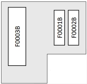
| Number | Amps [A] | Description |
|---|---|---|
| F0001B | 70A | Electric Power Steering (EPS) |
| F0002B | 60A | Radiator Fan – PWM |
| F0003B | 200A | Alternator |