Dacia Sandero – fuse box diagram
Year of manufacture: 2008, 2009, 2010, 2011, 2012.
Engine compartment
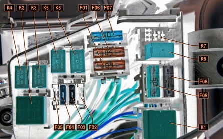
Description
| F01 (60A) | Power circuits: power supply to the ignition switch and all consumers supplied from the lock; exterior light switch |
| F02 (30A) | Power circuit for cooling fan relay K3 (in a car without air conditioning) |
| F03 (25A) | Power circuits: fuel pump and ignition coil relay K5; engine management system main relay K6 |
| F04 (5A) | Circuits: constant power supply to the ECU of the engine control system; winding of the main relay K6 of the engine control system |
| F05 (15A) | Not used |
| F06 (60A) | Power supply for fuse box in passenger compartment |
| F07 (40A) | Power circuits: air conditioning relay K4; relay K3 slow speed cooling fan (in air conditioned car); relay K2 fast speed cooling fan (in air conditioned car) |
| F08 (50A) and F09 (25A) | ABS ECU Chains |
Relay
- K1 – furnace fan relay, heater fan motor. See information in F36.
- K2 – fast cooling fan relay (for air conditioned cars), radiator fan motor.
- KZ – slow speed radiator fan relay (for cars with air conditioning) or radiator fan relay (for cars without air conditioning), radiator fan motor (for cars with air conditioning – via resistor).
- K4 – air conditioning relay, compressor solenoid clutch.
See information on F36. - K5 – fuel pump relay and ignition coil.
- K6 – main engine control system relay, oxygen sensor, speed sensor, fuel injectors, e/m adsorption bleed valve, relay coils K2, KZ, K4.
- K7 – headlight washer pump relay.
- K8 – fog light relay. See information in F31.
Passenger compartment
The fuse box is located at the end of the instrument panel.
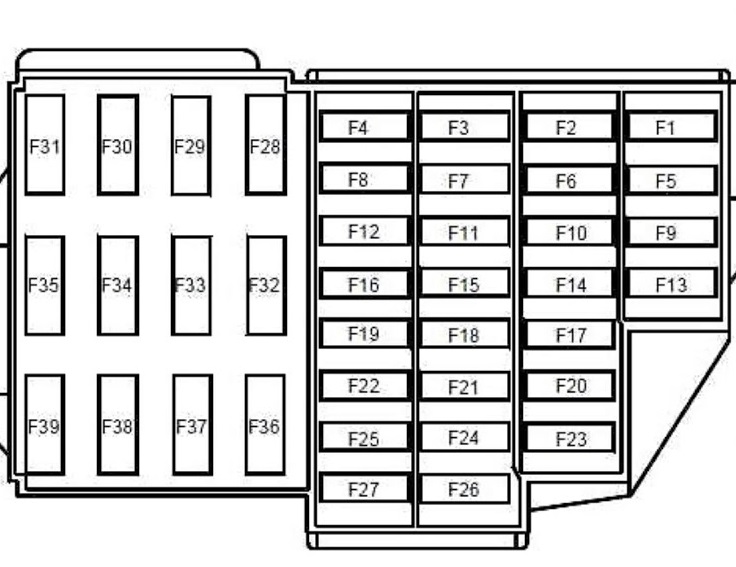
Description
| F01 (20A) | Windshield washer;
Rear window heater relay solenoid. |
| F02 (5A) | Power supply for the instrument cluster;
K5 relay winding for fuel pump and ignition coil; ECU control engine feed from ignition switch, |
| F03 (20A) | Brake lights;
Reversing lights; Windshield washer |
| F04 (10A) | Power circuits: airbag control unit; rotation signals; engine management system diagnostic connector; immobilizer coils |
| F09 (10A) | Power circuits: left headlights (dipped beam); dipped beam indicator on instrument panel; headlight washer pump |
| F10 (10A) | Right Headlight Unit Headlights (Dipped Beam) |
| F11 (10A) | Left (high beam) headlight assembly bulbs;
High beam indicator in instrument cluster |
| F12 (10A) | Headlights (High beam) |
| F13 (30A) F14 (30A) | Electric window chains for rear and front doors, respectively |
| F15 (10A) | ABS ECU |
| F17 (15A) | Sound Signal (horn) |
| F18 (10A) | Left side headlight bulbs;
Side lights for left rear light; Lamps for license plate illumination; Illumination of the instrument panel and controls on the instrument panel, console and floor tunnel lining; Sound signal from the switching unit. |
| F19 (7.5A) | Side lights for the right headlight;
Side lights for the right taillight; Lamps in the glove box |
| F20 (7.5A) | Lamps and indicator for switching on the rear fog lamp |
| F21 (5A) | Heating element circuit for exterior mirrors |
| F28 (15A) | Interior lamp shade;
Start light; Fixed power supply for the audio playback head unit, |
| F29 (15A) | Power circuits: alarm switch; indicator switch; intermittent wiper operation; central locking control; engine control diagnostic connector, |
| F30 (20A) | Central locking system power supply circuit |
| F31 (15A) | K8 Fog Light Relay Coil |
| F32 (30A) | Rear window defroster relay power supply circuit |
| F36 (30A) | Power circuit for heating fan relay K1 |
| F37 (5A) | Power circuits for the electric drives of exterior rear view mirrors |
| F38 (10A) | Lighter;
Powering the main unit for sound reproduction from the ignition switch; |
| F39 (30A) | Heater fan relay coil circuit |