Citroen Relay (2006-2014) – Fuse box diagram
Year of production: 2006, 2007, 2008, 2009, 2007, 2008, 2009, 2010, 2011, 2012, 2013, 2014.
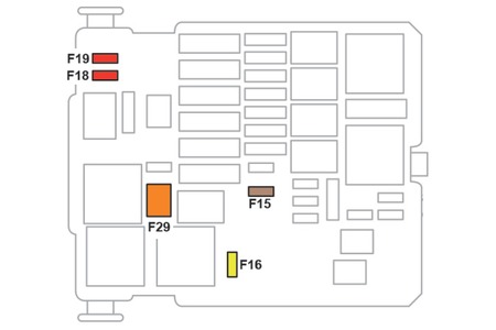
Lighter fuse (power socket) in Citroën Relay (2006-2014). Is fuse 15 in the fuse box in the engine compartment.
Driver-side dashboard fuses (v1).

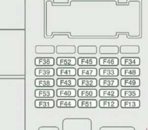 Citroen Relay – fuse box diagram – driver side dashboard fuses
No.
|
[A]
|
Description
|
| 12 |
7.5 |
Dipped-beam headlight on the right |
| 13 |
7.5 |
Left dipped beam headlight – headlight height adjuster |
| 31 |
7.5 |
Power supply to relay |
| 32 |
10 |
Minibus interior lighting – Warning lights |
| 33 |
15 |
12 volt rear socket. |
| 34 |
– |
Not used |
| 35 |
7.5 |
Reversing lights – diesel water sensor |
| 36 |
15 |
Door locking/unlocking unit |
| 37 |
7.5 |
Brake light switch – third traffic light – instrument panel |
| 38 |
10 |
Internal Relays |
| 39 |
10 |
Audio equipment – Diagnostic socket – Alarm siren – Programmable auxiliary heating control. |
| 40 |
15 |
Defrost: rear window (left side), mirror (passenger side) |
| 41 |
15 |
Defrost: rear window (right side), mirror (driver’s side) |
| 42 |
7.5 |
ABS controller and sensor – ESP sensor – Brake light switch. |
| 43 |
30 |
Windshield wiper motor |
| 44 |
20 |
Cigarette Lighter – 12 volt front output. |
| 45 |
7.5 |
Electric window and mirrors (driver’s side) – Electric passenger window |
| 46 |
– |
Not used |
| 47 |
20 |
Driver’s window motor |
| 48 |
20 |
Passenger window elevator motor |
| 49 |
7.5 |
Rain/sun sensor – Audio equipment – Driver’s window elevator motor – Alarm – Dashboard controls. |
| 50 |
7.5 |
Airbag and pretensioner assembly |
| 51 |
7.5 |
Tachograph – Cruise control – Air conditioning control. |
| 52 |
7.5 |
Passenger compartment relays |
| 53 |
7.5 |
Instrument panel – rear fog amplifiers |
Fuses in driver-side instrument panel (v2)

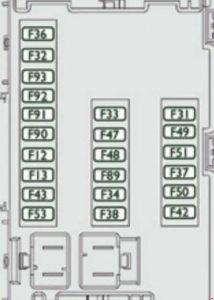 Citroen Relay – fuse box diagram – driver side instrument panel fuses
No.
|
[A]
|
Description
|
| 12 |
7.5 |
Right Dipped Beam |
| 13 |
7.5 |
Dipping light on the left |
| 31 |
5 |
Relay power supply |
| 32 |
7.5 |
Interior lighting |
| 33 |
20 |
Battery sensor |
| 34 |
20 |
Minibus interior lighting – hazard warning |
| 36 |
10 |
Audio system – Diagnostic socket – Alarm siren – Programmable auxiliary heating control – Air conditioning control – Tachograph – Battery. |
| 37 |
7.5 |
Brake light switch – third traffic light – instrument panel |
| 38 |
20 |
Central locking system |
| 42 |
5 |
ABS controller and sensor – ASR sensor – ESP sensor – brake light switch. |
| 43 |
20 |
Windshield wiper motor |
| 47 |
20 |
Driver’s window motor |
| 48 |
20 |
Passenger window elevator motor |
| 49 |
5 |
Audio system – dashboard controls |
| 50 |
7.5 |
Airbag and pretensioner assembly |
| 51 |
5 |
Tachograph – Cruise control – Air conditioning control – Reversing lights – Diesel water sensor. |
| 53 |
7.5 |
Dashboard |
| 89 |
– |
Not used |
| 90 |
7.5 |
Traffic Light Left |
| 91 |
7.5 |
Traffic Light Right |
| 92 |
7.5 |
Left fog light |
| 93 |
7.5 |
Right fog light |
Passenger pillar fuses

 Citroen Relay – fuse box diagram – passenger pillar fuses
No.
|
[A]
|
Description
|
| 54 |
– |
Not used |
| 55 |
15 |
Heated seats |
| 56 |
15 |
12 V socket. |
| 57 |
10 |
Programmable Auxiliary Heating |
| 57 |
10 |
Ventilation and heating engine under the driver’s seat |
| 58 |
15 |
Evaporation: left rear window |
| 58 |
10 |
Turning signals |
| 59 |
15 |
Evaporation: rear window right |
| 60 |
– |
Not used |
| 61 |
– |
Not used |
| 62 |
– |
Not used |
| 63 |
10 |
Programmable auxiliary heating switch |
| 64 |
– |
Not used |
| 65 |
30 |
Programmable auxiliary heating fan |
Fuses in engine compartment (v1)

 Citroen Relay – fuse box diagram – engine compartment
No.
|
[A]
|
Description
|
| 1 |
40 |
ABS / ESP Pump Supply |
| 2 |
50 |
Diesel Heating Unit |
| 3 |
30 |
Ignition Switch |
| 4 |
20 |
Programmable auxiliary heating burner |
| 5 |
20 |
Programmable relay that controls the auxiliary heating |
| 6 |
40/60 |
Fan Assembly (High Speed) |
| 7 |
40/50 |
Fan Assembly (Low Speed) |
| 8 |
40 |
Air Conditioning |
| 9 |
20 |
Windshield washer pump |
| 10 |
15 |
Horn |
| 11 |
7.5 |
Heating unit and diesel relay |
| 14 |
7.5 |
Traffic Light Right |
| 15 |
7.5 |
Left side high beam headlight |
| 16 |
7.5 |
Engine control unit |
| 17 |
10 |
Engine control unit |
| 18 |
7.5 |
Motor control unit |
| 19 |
7.5 |
A/C Compressor |
| 20 |
30 |
Headlight Washer Pump |
| 21 |
15 |
Fuel Pump Filling |
| 22 |
20 |
Engine control unit |
| 23 |
30 |
ABS / ESP solenoid valve supply |
| 24 |
– |
Not used |
| 30 |
15 |
Front fog lamps |
Fuses in engine compartment (v2)
 Citroen Relay – fuse box diagram – engine compartment
No.
|
[A]
|
Description
|
| 1 |
40 |
ABS / ESP Pump Supply |
| 2 |
50 |
Diesel heater assembly |
| 3 |
30 |
Ignition |
| 4 |
30 |
Headlight Washer Pump |
| 8 |
40 |
Assembling the cab fan |
| 9 |
15 |
12 volt rear socket. |
| 10 |
15 |
Horn |
| 14 |
15 |
Front 12 volt output. |
| 15 |
10 |
Lighter |
| 20 |
30 |
Washing pump |
| 21 |
15 |
Fuel Pump Filling |
| 24 |
15 |
Additional panel for ambulance – Mirrors |
| 30 |
15 |
Evaporation |