BMW 7 Series E65/E66/E67/E68 (2002-2008) – fuse box diagram
Year of manufacture: 2001, 2002, 2003, 2004, 2005, 2006, 2007, 2008.
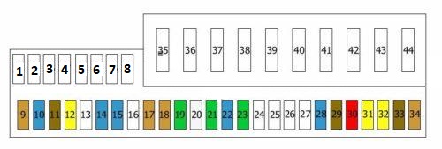
Fuse box in the glove box
Fuse box diagram
| No. | Amps [A] | Description |
|---|---|---|
| 1 | 20A | Auxiliary Heating System |
| 2 | 5A | Antenna |
| 3 | 30A | Body control unit |
| 4 | Not used | |
| 5 | 7,5A | Center console;
Information display; Rear information display; Phone. |
| 6 | 5A | CD Switch |
| 7 | 7,5A | Cruise Control Unit |
| 8 | 10 A | Dynamic drive |
| 9 | 5A | Tire Pressure Monitoring Unit (RDC) |
| 10 | 15A | Air conditioning control unit |
| 11 | 7,5A | Rear information display |
| 12 | 20A | Steering Column Switches |
| 13 | Not used | |
| 14 | 15A | Energy Saver Relay |
| 15 | 15A | Safety and gate module;
Driver’s seat; Passenger seat. |
| 16 | Not used | |
| 17 | 5A | Dynamic Stability Control (DSC);
Light Switch Module. |
| 18 | 5A | Reflector(s) |
| 19 | 30A | Left rear door control unit |
| 20 | 25A | Dynamic Stability Control (DSC) |
| 21 | 30A | Front left door control unit |
| 22 | 15A | Gearbox Control Unit |
| 23 | 30A | Driver’s seat control unit |
| 24 | Not used | |
| 25 | Not used | |
| 26 | Not used | |
| 27 | Not used | |
| 28 | 15A | Instrument Panel |
| 29 | 7,5A | On-board diagnostics |
| 30 | 10 A | Cooling fan for the electronic box (E-box);
Energy saving relay; Fuel heater relay; Starter Relay. |
| 31 | 20A | Front Lighter;
Rear Lighter. |
| 32 | 20A | 12V Rear Socket |
| 33 | 7,5A | Dashboard |
| 34 | 5A | Antenna amplifier |
| 35 | 40A | Windshield Wiper Motor |
| 36 | 50A | Light Module |
| 37 | 40A | Blower |
| 38 | Not used | |
| 39 | 50A | Dynamic Stability Control (DSC) |
| 40 | 60A | Integrated Control Unit |
| 41 | 50A | Fuel Heater Relay |
| 42 | 50A | Central Locking System |
| 43 | 50A | Cigarette Lighter Relay |
| 44 | 50A | Light Module |
Fuse box in engine compartment
Fuse box diagram (type 1)

| No. | Amps [A] | Description |
|---|---|---|
| 1 | 20A | Fuel vapor bleed solenoid(s);
Air flow meter; Rail pressure control valve; Hall sensor. |
| 2 | 20A | Crankcase heating compressor;
Vortex valve, solenoid; Intake manifold bypass valve; Oil level sensor; Heater. |
| 3 | 30A | Battery, control unit B+ DDE |
| 4 | Not used | |
| 5 | Not used | |
| R1 | DDE main relay | |
| R2 | Starter Relay | |
| R3 | Not used | |
| R4 | Not used |
Fuse box diagram (type 2)

| No. | Amps [A] | Description |
|---|---|---|
| 1 | 30A | Injectors DME with variable camshaft phasing (cylinders 5 – 8) |
| 2 | 20A | Fuel tank cap;
Camshaft synchronizing solenoid valve; Camshaft sensor. |
| 3 | 20A | Ignition Coils 1 – 4 |
| 4 | 20A | Ignition Coils 5 – 8 |
| 5 | 30A | Camshaft synchronizing solenoid valve;
Camshaft sensor; MAP-controlled engine cooling thermostat; Crankshaft position sensor; Air mass flow meter. |
| 6 | 20A | Injectors (cylinders 1 – 4) |
| 7 | 20A | Transmission control unit |
| 8 | 30A | Lambda probe before the catalytic converter; Lambda probe 2 before the catalytic converter; Lambda probe after catalytic converter; Lambda probe 2 after catalytic converter; Oil quality sensor. |
| 9 | 10 A | Diagnosis of leaks in the fuel tank;
Secondary air pump relay; Air mass flow meter; Electronic box (E-box); Cooling fan; Exhaust manifold flap; Energy saving relay. |
| 10 | 40A | Variable valve timing |
| 11 | 40A | Variable valve timing |
Fuse box in the trunk

F51 (15A) Heated windscreen relay
F52 (15A) Refrigerator
F53 (5A)
F54 (5A) Keyless entry and activation control module
F55 (30A) Seat heating control module, rear
F56 (30A) Electric Front Seats
F57 (15A)
F58 (30A) Door function control module, right front
F59 (5A) Parking Brake Control Module
F60 (30A) Door function control module, right rear
F61 (30A) Parking Brake Control Module
F62 (30A) Compressor Suspension Pump
F63 (20A) Sunroof control module
F64 -F65 (30A)
F66 (20A) Trailer Socket
F67 (30A)
F68 -F69 -F70 -F71 (5A)
F72 (7.5A) Suspension control module
F73 (15A)
F74 (30A) Trailer Control Module
F75 (30A)
F76 (10A)
F77 (5A)
F78 (30A)
F79 (10A)
F80 -F81 (50A) Trunk lid – open-close control module
F82 -F83 (40A)
F84 –